


4-11
Cisco uBR-3x10 RF Switch Hardware Installation and Cabling Guide
OL-1984-06
Chapter 4 Cabling the RF Switch With the Cisco uBR10012 CMTS Cable Interface Line Cards
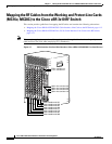
Mapping the RF Cables from the Working and Protect Line Cards (MC16x, MC28C) to the Cisco uBR 3x10 RF Switch
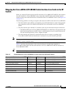
Mapping the Cisco uBR10-LCP2-MC16x (C,E,S) Cable Interface Line Cards to the
RF Switch
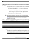
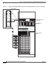
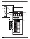
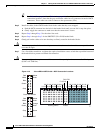
The following guidelines can help you map the RF cables between the Cisco uBR 3x10 RF Switch and
the Cisco uBR10-LCP2-MC16x cable interface line cards in the Cisco uBR10012 router:
• The RF switch ports labeled A to E and H to L on the header block connect to the upstream ports on
the Cisco uBR10-LCP2-MC16C, MC16E, or MC16S cable interface line cards installed in the
Cisco uBR10012 CMTS.
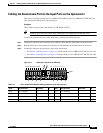
• The RF switch ports labeled F are used only for the downstream port connections.
–
The DS0 port on Cisco uBR10-LCP2-MC16x (C, E, S) line card is cabled first to the
upconverter and then from the upconverter to the RF switch. A 10-dB attenuator may be
required (due to a higher IF output) between the line cards and the upconverter.
• The MCX connection labeled N on the header block does not connect to anything in the RF switch
and should not be connected to any cable interface port either.
Note We recommend that the protect card be installed in slot 5/1 because this slot is directly below the
PROTECT section on the RF switch.
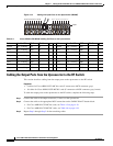
Table 4-1 provides one permutation of the connection between a header block attached to a
Cisco uBR 3x10 RF Switch and the cable interface ports on a Cisco uBR10-LCP2-MC16x line card
installed in a Cisco uBR10012 CMTS.
Note This sample mapping (or any other valid mapping method) is applicable to both working and protect
cable interface line cards when employing N+1 redundancy. The distinction between which line card
serves as the protect card and which ones serve as the working cards is decided by whether the header
block is plugged into a working (switch side) or protect group of interfaces on the RF switch and by the
configuration you specify using the information in the “N+1 Redundancy for the Cisco CMTS” chapter
of the Cisco Cable Modem Termination System Feature Guide.
Table 4-1 Sample Mapping of a Cisco uBR10-LCP2-MC16x Cable Interface Line Card to the Cisco uBR 3x10 RF Switch
Connect to the Cable Interface on the CMTS RFS
1
(Color)
1. RFS—RF switch, location of the MCX connection on the RF switch.
RFS (Color) Connect to the Cable Interface on the CMTS
US0 A (Red) H (Yellow) US4
US1 B (White) I (Violet) US5
US2 C (Blue) J (Unused upstream)
US3 D (Green) K (Unused upstream)
(Unused upstream) E L (Unused upstream)
DS0 F (Gray) M (Unused downstream)
(Unused downstream) G N (Not connected)