


5-5
Cisco uBR-3x10 RF Switch Hardware Installation and Cabling Guide
OL-1984-06
Chapter 5 Cabling the RF Switch With the Cisco uBR7246VXR CMTS
RF Cable Assemblies
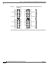
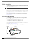
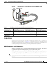
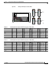
Figure 5-4 Cabling Solution for the Cisco RF Switch and Cisco uBR-MC28C Cards
Header Blocks
The header blocks are installed on the Cisco uBR 3x10 RF Switch. Individual cables are attached to the
MCX connectors in the header blocks (see Figure 5-4). The header blocks used in this cabling solution
are slightly beveled at the top for easy identification. In addition, the alignment pins on the header blocks
are offset, preventing you from accidentally connecting the header block upside down.
MCX Connectors and F-Connectors
MCXFP—75-ohm MCX connector available from WhiteSands Engineering or alternate. This connector
is attached to the end of the cable that terminates at the Cisco uBR 3x10 RF Switch.
ASFP or alternate—F-connectors available from WhiteSands Engineering. This connector is attached to
the end of the cables that terminate at the upstream and downstream ports on the cable interface line
cards. The output cabling kit includes 13 F-connectors to use for modification or repair.
Note An extraction tool used to remove MCX connectors from the header blocks is shipped with the
RF switch.
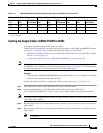
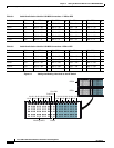
Table 5-1 Cable Types and the Number of Cable Bundles and Cables Required
Cables (from-to) Connector Type Cisco uBR-MC16x Cisco uBR-MC28C
US ports to RF ports F-connector to MCX connector 20 cable bundles (multicolor) 20 cable bundles (multicolor)
DS ports to UPx ports F-connector to F-connector 3 cable bundles (multicolor) 5 cable bundles (multicolor)
UPx ports to RF ports F-connector to MCX connector 20 single cables (gray, brown) 40 single cables (gray, brown)
RF switch output to
CABLE PLANT
MCX connector to F-connector 20 cable bundles (multicolor) 20 cable bundles (multicolor)
Alignment pins
Header block (top)
Bevel
From
upconverter
MCX
connectors
103016
F-connectors