


CHAPTER
1-1
Cisco uBR-3x10 RF Switch Hardware Installation and Cabling Guide
OL-1984-06
1
Cisco uBR-3x10 RF Switch Overview
This chapter describes the Cisco uBR 3x10 RF Switch. The chapter contains the following sections:
• About the Cisco uBR 3x10 RF Switch, page 1-1
• Hardware Component Descriptions, page 1-4
• Cable Kits, page 1-10
About the Cisco uBR 3x10 RF Switch
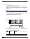
The Cisco uBR 3x10 RF Switch is designed to work with the Cisco uBR10012 CMTS or the
Cisco uBR7246VXR CMTS in a cable headend or hub to provide N+1 redundancy for applications such
as Voice over IP (VoIP).
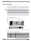
The Cisco uBR 3x10 RF Switch is a rack-mount unit that contains the RF combiners and splitters,
RF switches, and switch drivers. The RF switch uses Cisco RF Switch logic, and a Simple Network
Management Protocol (SNMP) control interface. The Cisco uBR 3x10 RF Switch can be controlled
using SNMP from the Cisco uBR10012 CMTS or the Cisco uBR7246VXR CMTS.
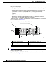
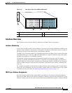
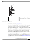
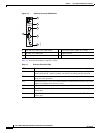
Chassis Features
The Cisco uBR 3x10 RF Switch chassis features:
• One power-supply module that provides either 100 to 240 VAC or –48 to –60 VDC power to the
Cisco uBR 3x10 RF Switch chassis.
• One Ethernet controller module that provides SNMP control for automatic redundancy channel
selection.
• Ten upstream (low-frequency) switch modules that provide 75-ohm termination and automatic
upstream redundancy switching from 5 to 70 MHz.
• Three downstream (high-frequency) switch modules that provide 75-ohm termination and automatic
downstream redundancy switching from 54 to 860 MHz.
• Eight power divider assemblies used to route signals to and from the appropriate upstream or
downstream assemblies or protect interfaces.
• One midplane assembly that distributes power and control signals from the power supply and
Ethernet controller to the upstream and downstream switch assemblies.