


5-8
Cisco uBR-3x10 RF Switch Hardware Installation and Cabling Guide
OL-1984-06
Chapter 5 Cabling the RF Switch With the Cisco uBR7246VXR CMTS
Connecting the Cables (Cisco uBR-MC16x Card)
Connecting the Cables (Cisco uBR-MC16x Card)
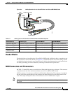
This section describes one method of cable management using the sample configuration for the
Cisco uBR7246VXR with the Cisco uBR-MC16x (C, E, S, U, X) line cards installed.
Tip Cable the line card to the RF switch header block one card at a time.
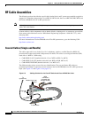
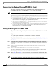
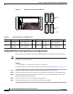
RF cables are connected to the CMTS, PROTECT, and CABLE PLANT sections on the rear panel of the
Cisco uBR 3x10 RF Switch using a header block. There are:
• 16 RF connection groups under CMTS—These groups of RF cables connect to cable interface line
cards designated as the working line cards and to IF-to-RF upconverters.
• 4 RF connection groups under PROTECT—These groups of RF cables connect to cable interface
line cards designated as the protect line cards.
• 16 RF connection groups under CABLE PLANT—These groups of RF cables connect to the coaxial
or fiber-optic cable transceivers (in the upstream direction) and IF-to-RF upconverters (in the
downstream direction) at the cable headend or HUB.
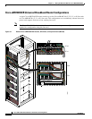
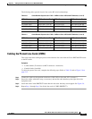
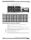
Cabling the Working Line Card (VXR1–VXR4)
This section describes cabling the working line cards from the Cisco uBR7246VXR routers to the RF
switch.
Equipment
• 16 cable bundles—4 per router (F-connector to MCX connector—multicolor)
• 16 header blocks (installed)
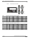
To cable the working line cards, complete the following steps. Refer to Table 5-2, Table 5-3, Table 5-4,
and Table 5-5.
Step 1 Connect the cables to the upstream connectors (US0–US5) on the line cards in VXR1. Tighten the
F-connectors to a value between 10 (recommended) and 15 (maximum) inch-pounds (1.1298 nm and
1.7339 nm).
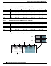
Step 2 Secure the cables with cable wrap, as necessary, and run the cable bundles up the left side of the
equipment rack.
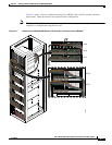
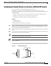
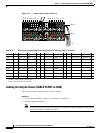
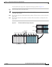
Step 3 Install the cables in the CMTS header block in the order that they were mapped.
a. Push the MCX connector into the hole in the header block until you can feel it snap into place.
b. Gently wiggle the connector to make sure that the connection is secure.
Step 4 Repeat Step 1 through Step 3 for each line card in each Cisco uBR7246VXR (VXR2 through VXR4).
Note One cable bundle is used for the US ports on each card. DS ports use a different cable bundle.