


5-15
Cisco uBR-3x10 RF Switch Hardware Installation and Cabling Guide
OL-1984-06
Chapter 5 Cabling the RF Switch With the Cisco uBR7246VXR CMTS
Connecting the Cables (Cisco uBR-MC16x Card)
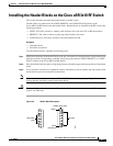
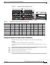
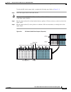
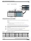
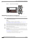
To cable the RF switch output cables, complete the following steps. Refer to Figure 5-11.
Step 1 Install the output cables in the header blocks.
Note The output cables (CABLE PLANT) on the Cisco uBR 3x10 RF Switch are cabled in the reverse order
of the input cables (CMTS).
Step 2 Run the output cables (H–A) from header blocks to splitters, US laser receivers, or the low side of the
diplex filters
Step 3 Run the output cables (F) to the splitters or combiners, DS laser transmitters, or the high side of the
diplex filters.
Figure 5-11 RF Switch Cable Plant Outputs (Turquoise)
103930
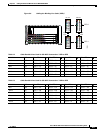
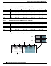
Working CMTS Protect
RFS-2
1A-1H
2A-2H
3A-3H
4A-4H
5A-5H
6A-6H
7A-7H
8A-8H
P1A-P1H
P2A-P2H
8H-8A
RFS-1
7H-7A
6H-6A
5H-5A
4H-4A
3H-3A
2H-2A
1H-1A