


6-6
Cisco uBR-3x10 RF Switch Hardware Installation and Cabling Guide
OL-1984-06
Chapter 6 Troubleshooting
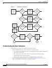
Troubleshooting the Installation and Setup
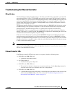
Troubleshooting Upstream and Downstream Switch Modules
Each upstream and downstream switch module has four LEDs that indicate the working status of the
port. The upstream switch module operates over the frequency range of 5 to 70 MHz. The downstream
(high-frequency) switch module operates over the frequency range of 54 to 860 MHz. During normal
system operation, upstream switches all direct traffic to their respective default termination interfaces.
Each switch module takes on eight signal inputs from the power splitter and routes the signal to a protect
output, or splits the inputs into two groups of four inputs and sets up the switch to select one of four
inputs as a protect output. The relays are electromechanical and controlled through the power interface
connector.
The switch card should provide a minimum of 60 dB of isolation from connector port to connector port
during normal operation and more than 20 dB when operating in protect mode.
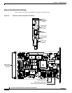
Status LEDs
Each upstream and downstream switch module has four LEDs on the faceplate that indicate the working
status of the port as described in Table 6-5.
When an upstream or downstream switch module initially boots, the LEDs briefly cycle on in sequence.
After the bootup,
• The PROTECT1/PROTECT2 LEDs are on/off for single protect mode, or on/on for dual protect
mode. The LED color reflects the current setting of the module protect mode switch—green for idle
or yellow for any protect position.
• The ERROR1/ERROR2 LEDs stay on until the Ethernet controller detects and enumerates the
switch module.
• If either of these LEDs remain on (yellow) after the system boot sequence, there is either a
communications failure or a switch position failure. Use the test module command to diagnose
failure.
If you are unable to resolve the problem, refer to the “Obtaining Technical Assistance” section on
page 12 for information on contacting Cisco technical assistance.
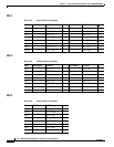
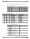
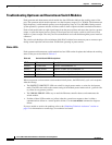
Table 6-5 Switch Board LED Descriptions
LED Name Color Description
Protect 1 Green/Yellow Indicates CMTS/PROTECT 1
Protect 2 Green/ Yellow Indicates CABLE PLANT/PROTECT 2
Error 1 Off/Yellow Indicates a channel problem in 1
Error 2 Off/Yellow Indicates a channel problem in 2