


3-17
Cisco uBR-3x10 RF Switch Hardware Installation and Cabling Guide
OL-1984-06
Chapter 3 Installing the Cisco RF Switch
Connecting Power
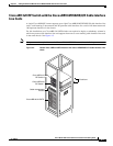
Connecting DC Power to the Power Supply
Warning
Before performing any of the following procedures, ensure that power is removed from the DC circuit.
Statement 1003.
Warning
A readily accessible two-poled disconnect device must be incorporated in the fixed wiring.
Statement
1022.
Warning
This product requires short-circuit (overcurrent) protection, to be provided as part of the building
installation. Install only in accordance with national and local wiring regulations.
Statement 1045.
Note The color coding of the DC-input power supply leads depends on the color coding of the DC power
source at your site. Typically, green or green-yellow is used for ground, black is used for +48V (return),
and red or white is used for –48V. Ensure that the lead color coding you choose for the DC-input power
supply matches lead color coding used at the DC power source.
Caution Each DC-input power supply has an electrical current rating of 0.7 A, 20 VA. Use a minimum of
14 AWG (2.5 mm
2
) wire for the input to each DC-input power supply. The power input must be protected
by a 15 A circuit breaker or fuse that is in compliance with your local electric regulations.
Equipment
• 14 AWG (2.5 mm
2
) wire
• Wire stripper
• AC to DC power source
• 7/16-inch flat-blade screwdriver
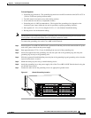
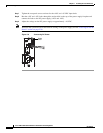
Step 1 Ensure that the –48V and +48V leads are disconnected from the power source.
Step 2 Check that the power switch on the power supply is in the OFF (0) position.
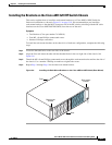
Step 3 Ensure that the unit is properly grounded. See the “Grounding the Cisco uBR 3x10 RF Switch” section
on page 3-14.
Step 4 Using a wire stripper, strip approximately 0.25 in. (7 mm) from the –48V and +48V leads.
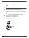
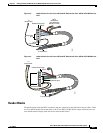
Step 5 Insert the stripped end of the +48V lead all the way into the +48V lead receptacle and tighten the
receptacle screw using the same 3/16-inch flat-blade screwdriver.
Step 6 Repeat Step 4 and Step 5 for the –48V lead.
Caution If any exposed wire at the stripped end of a lead is visible after inserting the lead into its receptacle,
remove the lead from the receptacle, use the wire stripper to cut the stripped end of the lead, and repeat
Step 4 and Step 5, if necessary.