


2-9
Cisco uBR-3x10 RF Switch Hardware Installation and Cabling Guide
OL-1984-06
Chapter 2 Preparing for Installation
Tools for Installation
Caution To prevent the chassis from overheating, never install the Cisco uBR 3x10 RF Switch in an enclosed rack
or room that is not properly ventilated or air conditioned. The Cisco uBR 3x10 RF Switch overheats if
the input air temperature reaches 105°F (41°C).
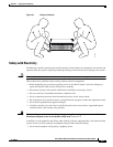
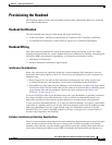
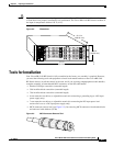
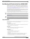
Figure 2-2 Dimensions
Tools for Installation
Your Cisco uBR 3x10 RF Switch is fully assembled at the factory; no assembly is required. However,
you need the following tools and equipment to install rack-mount brackets on the Cisco uBR 3x10
RF Switch chassis, install the chassis in the rack, and if you are using nonprepopulated cable bundles,
complete assembly of unterminated MCX connectors on the RF cable bundle:
• Number 2 Phillips screwdriver (extended length)
• 3/16-inch flat-blade screwdriver (extended length)
• 7/16-inch flat-blade screwdriver (extended length)
• 8-mm wrench or nut driver, or adjustable wrench (for connecting a grounding lug to a DC-input
power supply only)
• 7-mm wrench or nut driver, or adjustable wrench (for connecting the DC-input power lead
strain-relief cover to a DC-input power supply only)
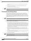
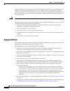
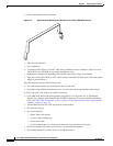
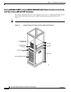
• MCX connector removal tool (see Figure 2-3), for removing MCX connectors from header blocks
and universal cable holders (UCHs)
Figure 2-3 MCX Connector Removal Tool
82134
5.22 in.
(132.59 mm)
15.12 in.
(384.05 mm)
17.0 in.
(431.8 mm)
72510