


4-16
Cisco uBR-3x10 RF Switch Hardware Installation and Cabling Guide
OL-1984-06
Chapter 4 Cabling the RF Switch With the Cisco uBR10012 CMTS Cable Interface Line Cards
Connecting the RF Cables (MC16x, MC28C Line Cards)
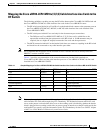
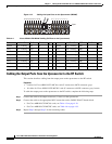
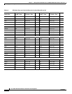
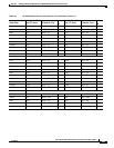
Tip See Table 4-2 on page 4-13 and Table 4-1 on page 4-11 for cable interface and CMTS
connection locations. Note that the gray and brown cables have F-connectors instead of MCX
connectors. These cables are used to connect to the upconverter (UPx).
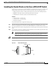
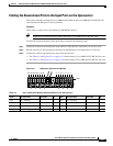
Step 3 Install the cables in the CMTS header block in the order that they were mapped.
a. Push the MCX connector into the hole in the header block until you can feel it snap into place.
b. Gently wiggle the connector to make sure that the connection is secure.
Step 4 Repeat Step 1through Step 3 for the other line cards.
Step 5 Repeat Step 1 through Step 3 for the PROTECT (P1A–P1H) header block.
Step 6 Gently pull on the cables to be sure that they are firmly seated in the header blocks.
Caution To ensure proper installation and avoid poor connections, be sure that the cables are not positioned at
too acute an angle.
Step 7 Use a flat-blade screwdriver to tighten the captive installation screws at both the top and the bottom of
the header block to prevent accidental disconnection.
Caution Do not overtighten the captive screws. We recommend that you tighten the screws to 5 to 7 inch-pounds
(0.5647 to 0.7909 Nm).
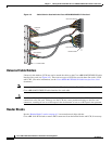
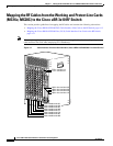
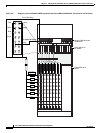
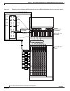
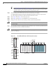
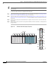
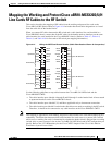
Figure 4-10 Cisco uBR 3x10 RF Switch—MCX Connection Locations
103304
Working CMTS Protect
1A-1H
2A-2H
3A-3H
4A-4H
5A-5H
6A-6H
7A-7H
8A-8H
P1A-P1H
P2A-P2H
8H-8A
7H-7A
6H-6A
5H-5A
4H-4A
3H-3A
2H-2A
1H-1A
AH
BI
CJ
DK
E L
FM
G N
Red
White
Blue
Green
Cisco uBR-MC28C
YellowYellow
Violet
Gray
AH
BI
CJ
DK
E L
FM
G N
Red
White
Blue
Green
YellowYellow
Violet
Gray
Cisco uBR-MC16x
Orange
Black
Brown