


4-15
Cisco uBR-3x10 RF Switch Hardware Installation and Cabling Guide
OL-1984-06
Chapter 4 Cabling the RF Switch With the Cisco uBR10012 CMTS Cable Interface Line Cards
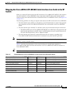
Connecting the RF Cables (MC16x, MC28C Line Cards)
Connecting the RF Cables (MC16x, MC28C Line Cards)
The RF cables are connected between the Cisco uBR10-LCP2-MC16x (C, E, S) line cards or the
Cisco uBR10-LCP2-MC28C line cards, and the CMTS and PROTECT portions of the
Cisco uBR 3x10 RF Switch in bundles of RF cables. The cables terminate at header blocks that connect
to the RF switch at one of the following locations:
• CMTS—These groups of RF cables connect to cable interface line cards designated as the working
line cards and to IF-to-RF upconverters.
• PROTECT—These groups of RF cables connect to cable interface line cards designated as the
protect line cards.
For information about cabling to the Vecima HD4040 upconverter, refer to the “Cabling the Output Ports
from the Upconverter to the RF Switch” section on page 4-18.
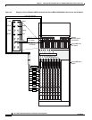
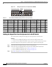
Note CABLE PLANT connections are made after all the other connections have been made. The CABLE
PLANT RF cables connect to the coaxial or fiber-optic cable transceivers (in the upstream direction) and
IF-to-RF upconverters (in the downstream direction) at the cable headend or hub.
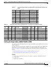
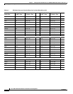
For cable mapping information, refer to:
• “Mapping the Cisco uBR10-LCP2-MC28C Cable Interface Line Cards to the RF Switch” section on
page 4-13.
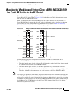
• “Mapping the Cisco uBR10-LCP2-MC16x (C,E,S) Cable Interface Line Cards to the RF Switch”
section on page 4-11.
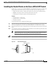
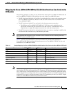
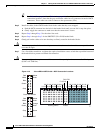
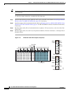
Cabling the Working and Protect Line Cards to the RF Switch
This section describes cabling the working and protect line cards from the Cisco uBR10012 CMTS to
the RF switch.
Tip Use the card in slot 5/1 for the protect card. See Figure 4-7 on page 4-10 for slot number locations.
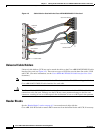
Equipment
• 8–RF cable bundles (CAB-RFSW-3X10-T)
• 8–neader blocks (installed)
• Flat-blade screwdriver (extended length)
To cable the card, complete the following steps.
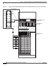
Step 1 Connect the cables to the cable interface line card connectors (upstream and downstream).
Note We recommend that you tighten the F-connectors to a value between 10 (recommended) and 15
(maximum) inch-pounds (1.1298 and 1.7339 Nm).
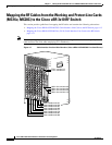
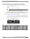
Step 2 Run the cable bundle (behind the cable management bracket if it was installed) up to the CMTS header
blocks on the RF switch.