


5-7
Cisco uBR-3x10 RF Switch Hardware Installation and Cabling Guide
OL-1984-06
Chapter 5 Cabling the RF Switch With the Cisco uBR7246VXR CMTS
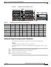
Installing the Header Blocks on the Cisco uBR 3x10 RF Switch
Installing the Header Blocks on the Cisco uBR 3x10 RF Switch
This section describes attaching the header blocks to the RF switch.
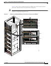
The RF cables are connected to the CMTS, PROTECT, and CABLE PLANT portions of the
Cisco uBR 3x10 RF Switch using the header blocks. Header blocks are installed on the RF switch at the
following locations:
• CMTS—RF cables connect to working cable interface line cards and to IF-to-RF upconverters.
• PROTECT—RF cables connect to protecting cable interface line cards
• CABLE PLANT—RF cables connect to the cable headend or hub.
Equipment
• 36 header blocks
• Flat-blade screwdriver
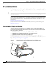
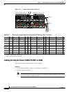
To install header blocks, complete the following steps.
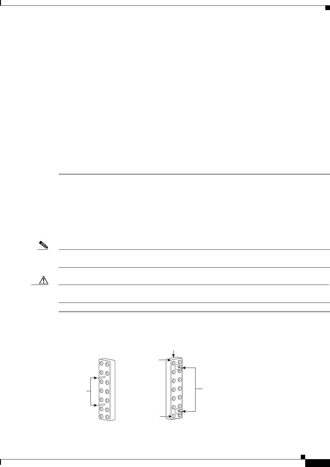
Step 1 With the beveled edge of the header block at the top, line up the two alignment pins on the header block
with the two holes corresponding to the RF connector group under the CMTS, PROTECT, or CABLE
PLANT section of the Cisco uBR 3x10 RF Switch.
Step 2 Press the header block into place, using equal pressure on both the upper and lower portions of the header
block.
Step 3 Use a flat-blade screwdriver to tighten the captive installation screws at both the top and bottom of the
header block to prevent accidental disconnections.
Note Tighten the header blocks to the Cisco uBR 3x10 RF Switch only after gently pulling on the cables to
be sure that they are firmly seated in the header block.
Caution Do not overtighten the captive screws. We recommend that you tighten the screws to 5 to 7 inch-pounds
(0.5647 to 0.7909 nm)
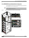
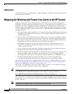
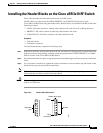
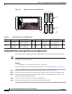
Figure 5-5 Header Block Description
Screws
Header block (top)
Bevel
95808
MCX
connectors
Alignment
pins