


4-27
Cisco uBR-3x10 RF Switch Hardware Installation and Cabling Guide
OL-1984-06
Chapter 4 Cabling the RF Switch With the Cisco uBR10012 CMTS Cable Interface Line Cards
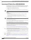
Connecting the RF Cables (Cisco uBR10-MC5X20S/U/H)
For cabling locations, refer to:
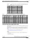
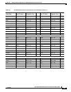
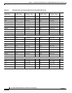
• Table 4-7 on page 4-22 for slot 8/0 and 8/1 working line card RF switch connections.
• Table 4-8 on page 4-23 for slot 7/0 and 7/1 working line card RF switch connections.
• Table 4-9 on page 4-24 for slot 6/0 and 6/1 working line card RF switch connections.
• Table 4-10 on page 4-25 for slot 5/0 and 5/1 working and protect line card RF switch connections.
Step 4 Gently pull on the cables to be sure that they are firmly seated in the header blocks.
Step 5 Use a flat-blade screwdriver to tighten the captive installation screws at both the top and bottom of the
header block to prevent accidental disconnections.
Caution Do not over-tighten the captive screws. We recommend that you tighten the captive screws to 5 to 7
inch-pounds (0.5647 to 0.7909 Nm).
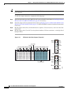
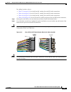
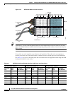
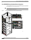
Figure 4-15 Cisco uBR 3x10 RF Switch Header Block with Cables Installed
Caution To ensure proper installation and avoid poor connections, be sure that the cables are not positioned at
too acute an angle.
82967
Bevel
Back
Front
Captive
installation
screws
Alignment
pins