


1-9
Cisco uBR-3x10 RF Switch Hardware Installation and Cabling Guide
OL-1984-06
Chapter 1 Cisco uBR-3x10 RF Switch Overview
Hardware Component Descriptions
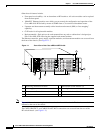
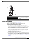
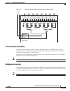
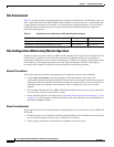
Figure 1-7 RF Switch Module Schematic (Upstream and Downstream)
Power Divider Assembly
The power divider assembly contains 16 splitters that operate from 5 to 860 MHz. The board also
contains four protect feed-through connections. The power splitter provides a minimum of 60 dB of
isolation from connector port to connector port.
The power divider assemblies are connected directly to the upstream and downstream card assemblies
through an access area in the midplane card.
Note This assembly is not a field-replaceable unit (FRU).
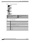
Midplane Assembly
The midplane assembly is located in the center of the chassis and connects the upstream and downstream
to the power supply and Ethernet card assemblies. This card distributes +12V power, ground, and the I
2
C
control signals to the 14 switch card positions available.
Note This assembly is not a field-replaceable unit (FRU).
95901
Memory
and
drivers
Switch board
Protect
12
8
out
in in
7
out
in
6
out
in
5
out
in
4
out
in
3
out
in
2
out
in
1
out