


5-11
Cisco uBR-3x10 RF Switch Hardware Installation and Cabling Guide
OL-1984-06
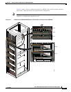
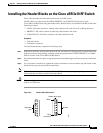
Chapter 5 Cabling the RF Switch With the Cisco uBR7246VXR CMTS
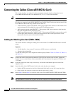
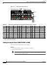
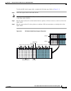
Connecting the Cables (Cisco uBR-MC16x Card)
The following tables provide chassis–line card to RF switch relationships.
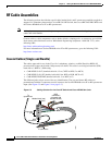
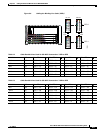
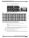
Cabling the Protect Line Cards (VXR5)
This section describes cabling the protect cable interface line cards from the Cisco uBR7246VXR router
to the RF switch.
Equipment
• 4 cable bundles (F-connector to MCX connector—multicolor)
• 4 header blocks (installed)
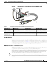
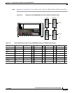
To cable the protect line cards, complete the following steps. Refer to Table 5-8 and to Figure 5-8 on
page 5-12.
Step 1 Connect the cables to the upstream connectors (US0–US5) on line card–LC1 on router 5.
Step 2 Secure the cables with cable wrap, as necessary, and run the cable bundles up the right side of the
equipment rack.
Step 3 Install the cables in the PROTECT header block in the order that they were mapped. See Figure 5-8.
Step 4 Repeat Step 1 through Step 3 for all the line cards in VXR5 (PROTECT).
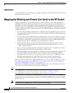
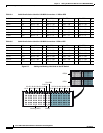
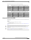
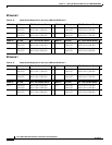
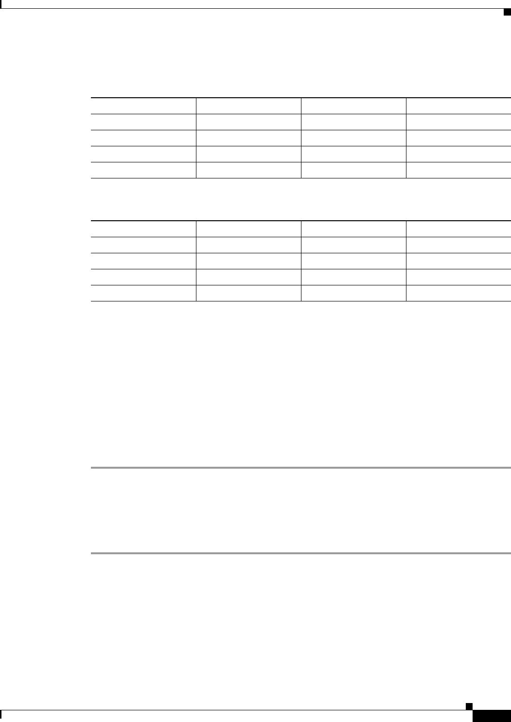
Table 5-6 Cable Bundle Sequence for VXR1—VXR2 to Cisco uBR 3x10 RF Switches (1 and 2)
VXR1–LC RFS Slot (Header Block) VXR2–LC RFS Slot (Header Block)
LC1(US0–US5) RFS-2 Slot 1 (1A–1I) LC1(US0–US5) RFS-2 Slot 2 (2A–2I)
LC2(US0–US5) RFS-2 Slot 5 (5A–5I) LC2(US0–US5) RFS-2 Slot 6 (6A–6I)
LC3(US0–US5) RFS-1 Slot 1 (1A–1I) LC3(US0–US5) RFS-1 Slot 2 (2A–2I)
LC4(US0–US5) RFS-1 Slot 5 (5A–5I) LC4(US0–US5) RFS-1 Slot 6 (6A–6I)
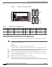
Table 5-7 Cable Bundle Sequence for VXR3—VXR4 to Cisco uBR 3x10 RF Switches (1 and 2)
VXR3–LC RFS Slot (Header Block) VXR4–LC RFS Slot (Header Block)
LC1(US0–US5) RFS-2 Slot 3 (3A–3I) LC1(US0–US5) RFS-2 Slot 4 (4A–4I)
LC2(US0–US5) RFS-2 Slot 7 (7A–7I) LC2(US0–US5) RFS-2 Slot 8 (8A–8I)
LC3(US0–US5) RFS-1 Slot 3 (3A–3I) LC3(US0–US5) RFS-1 Slot 4 (4A–4I)
LC4(US0–US5) RFS-1 Slot 7 (7A–7I) LC4(US0–US5) RFS-1 Slot 8 (8A–8I)