


5-19
Cisco uBR-3x10 RF Switch Hardware Installation and Cabling Guide
OL-1984-06
Chapter 5 Cabling the RF Switch With the Cisco uBR7246VXR CMTS
Connecting the Cables (Cisco uBR-MC28x Line Card)
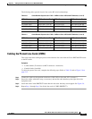
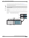
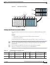
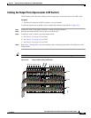
Figure 5-13 Cisco uBR 3x10 RF Switch
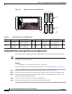
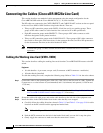
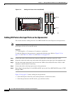
Cabling the Protect Line Cards (VXR 5)
This section describes cabling the protect line cards from the Cisco uBR7246VXR router to the RF
switch.
Equipment
• 4 cable bundles—1 per router (F-connector to MCX connector—multicolor)
• 4 header blocks (installed)
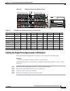
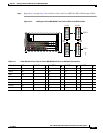
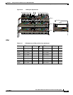
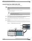
To cable the protect line cards, complete the following steps. Refer to Table 5-14 and Figure 5-14.
Step 1 Connect the cables to the upstream connectors (US0–US3, US0–US3) on line card, LC1 in router 5.
Step 2 Secure the cables with cable wrap, as necessary, and run the cable bundles up the right side of the
equipment rack.
Step 3 Install the cables in the PROTECT header block in the order that they were mapped.
Step 4 Repeat Step 1 through Step 3 for all the line cards in VXR5 (PROTECT).
103930
Working CMTS Protect
RFS-2
1A-1H
2A-2H
3A-3H
4A-4H
5A-5H
6A-6H
7A-7H
8A-8H
P1A-P1H
P2A-P2H
8H-8A
RFS-1
7H-7A
6H-6A
5H-5A
4H-4A
3H-3A
2H-2A
1H-1A
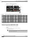
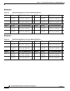
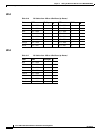
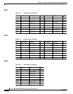
Table 5-14 RF Switch Slots for the PROTECT Cards
VXR5–LC US Ports RFS–2—PROTECT Slot
D
VXR5–LC US Ports RFS–1—PROTECT Slot
D
LC1 US0–US3
US0–US3
RFS-2—P2 (A–D)
RFS-2—P2 (H–K)
LC3 US0–US3
US0–US3
RFS-1—P2 (A–D)
RFS-1—P2 (H–K)
LC2 US0–US3
US0–US3
RFS-2—P1 (A–D)
RFS-2—P1 (H–K)
LC4 US0–US3
US0–US3
RFS-1—P1 (A–D)
RFS-1—P1 (H–K)