


1-7
Cisco uBR-3x10 RF Switch Hardware Installation and Cabling Guide
OL-1984-06
Chapter 1 Cisco uBR-3x10 RF Switch Overview
Hardware Component Descriptions
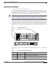
Upstream Switch Modules
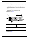
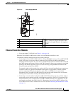
• Cisco part number 74-2622-01 (See Figure 1-5.)
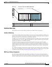
There are 10 upstream switch modules used in the Cisco uBR 3x10 RF Switch. The module operates
over the from 5 to 70 MHz. Each module has ten 75-ohm inputs accessed through the MCX connectors
on the backpanel of the RF switch (see Figure 1-2 on page 1-3). During normal system operation, all of
the upstream switches direct traffic to their respective default termination interfaces.
Note Upstream cables from the cable interface line cards are plugged into the CMTS MCX connections in the
rear of the Cisco uBR 3x10 RF Switch. See Chapter 4, “Cabling the RF Switch With the Cisco
uBR10012 CMTS Cable Interface Line Cards,” for more information about cabling the RF switch.
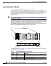
The upstream switch module takes the signal inputs (eight) from the power splitter and routes one of the
eight to a protect output, or splits the inputs into two groups of four and sets up the switches to select
one input (of a group of four) as a protect output. The relays are electromechanical, latching relays that
are controlled through an I
2
C interface. The switch card provides a minimum of 60 dB of isolation from
connector port to connector port during normal operation and more than 20 dB when operating in protect
mode.
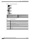
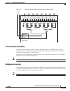
Figure 1-5 Upstream Switch Card
Each upstream switch has a set of four LEDs that indicate the working status of the port as described in
Table 1-2.
103288
Captive screw Captive screw
Table 1-2 Upstream Switch Board LED Descriptions
LED Name Color Description
Protect 1 Green/Yellow Indicates CMTS/PROTECT 1
Protect 2 Green/ Yellow Indicates CABLE PLANT/PROTECT 2
Error 1 Off/Yellow Indicates a channel problem 1
Error 2 Off/Yellow Indicates a channel problem 2