


3-7
Cisco uBR-3x10 RF Switch Hardware Installation and Cabling Guide
OL-1984-06
Chapter 3 Installing the Cisco RF Switch
Rack-Mounting the RF Switch with the Cisco uBR10012 CMTS
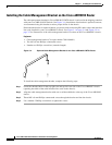
Step 3 Thread the M5 x 8-mm Phillips countersunk screws through the rack-mount bracket and into the side of
the chassis. Use a number 2 Phillips screwdriver to tighten the screws.
Step 4 Repeat Step 1 through Step 3 for the other rack-mount bracket.
Installing the RF Switch in the Rack with the Cisco uBR10012 CMTS
To prevent injury, review the safety precautions in Chapter 2, “Preparing for Installation,” before
installing the Cisco uBR 3x10 RF Switch in a rack.
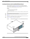
Note For this configuration, the Cisco uBR 3x10 RF Switch is placed so that the MCX connection side of the
switch is facing in the same direction as the cable interface line cards.
Caution Because the brackets support the weight of a fully populated chassis (36.6 lb [16.6 kg]), be sure to use
all four screws to fasten the two rack-mount brackets to the rack posts.
Note If you are installing two RF switches, leave one rack unit (1 RU) between the two switches.
Equipment
• Four 1/32 x 3/8 slotted screws (eight for two RF switches)
• 7/16-inch flat-blade screwdriver (extended length)
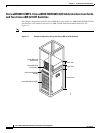
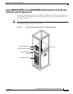
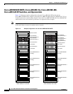
To install the chassis in the rack, refer to the sample configuration appropriate to your installation (see
Figure 3-1 on page 3-4, or Figure 3-2 on page 3-5 and complete the following steps:
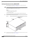
Step 1 Ensure that all the components in the RF switch are securely installed (captive screws are tight).
Step 2 Make sure that the rack is stabilized, if necessary.
Tip Two people should perform Step 3 through Step 6.
Step 3 Position the RF switch so that the upstream and downstream modules are facing the front of the router.
Step 4 Slide the switch into the rack, pushing it back until the brackets (installed at the front of the RF switch
chassis) meet the mounting strips or posts on both sides of the equipment rack.
Step 5 While keeping the brackets flush against the posts or mounting strips, position the RF switch so the holes
in the brackets are aligned with those in the mounting strips.
Step 6 Insert all four screws (two on each side) through the brackets and into the mounting strip and tighten.
Insert the bottom screws first.
Step 7 Repeat Step 3 through Step 6 for the second RF switch, if necessary.