


C-3
Cisco uBR7100 Series and Cisco uBR7100E Series Universal Broadband Router Hardware Installation Guide
OL-5916-01
Appendix C Cable Specifications
Console and Auxiliary Port Cables and Pinouts
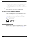
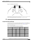
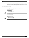
Figure C-2 RJ-45 Rollover Cable Identification
The colored wires at one connector are in the reverse order at the other connector (reverses pins 1 and 8,
2 and 7, 3 and 6, 4 and 5, 5 and 4, 6 and 3, 7 and 2, 8 and 1).
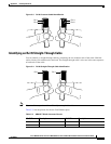
The wires of the straight-through cable are in the same sequence at both ends of the cable.
Note If your cable was purchased from Cisco Systems, pin 8 is white.
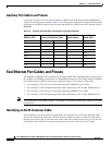
Console Port Cables and Pinouts
Use the RJ-45-to-RJ-45 rollover cable and RJ-45-to-DB-9 female DTE adapter (labeled TERMINAL) to
connect the console port to a PC running terminal emulation software. Table C-1 lists the signals and
pinouts for the asynchronous serial console port, the RJ-45-to-RJ-45 rollover cable, and the
RJ-45-to-DB-9 female DTE adapter.
Pin 1
Pin 8
H3824
Pin 1 and pin 8
should be the
same color
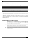
Table C-1 Console Port Signaling and Cabling Using a DB-9 Adapter
Console Port (DTE) RJ-45-to-RJ-45 Rollover Cable
RJ-45-to-DB-9
Terminal Adapter Console Device
Signal RJ-45 Pin RJ-45 Pin DB-9 Pin Signal
RTS 1
1
1. Pin 1 is connected internally to pin 8.
88 CTS
DTR 276 DSR
TxD 362 RxD
GND455 GND
GND545 GND
RxD 633 TxD
DSR 724 DTR
CTS 8
1
17 RTS