


1-19
Cisco uBR7100 Series and Cisco uBR7100E Series Universal Broadband Router Hardware Installation Guide
OL-5916-01
Chapter 1 Product Overview
Functional Overview
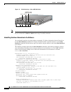
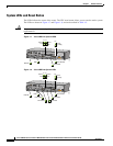
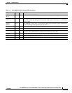
Table 1-5 Cisco uBR7100 Series System LED Descriptions
LED Label Color State Function
ACT 0
ACT 1
Green On 10BASE-T/100BASE-TX Ethernet ports are transmitting or receiving packets (activity).
LNK 0
LNK 1
Green On 10BASE-T/100BASE-TX Ethernet ports have established a valid link with the network.
This LED remains off during normal operation of the router, unless there is an incoming
carrier signal.
SLOT 0
SLOT 1
Green On The PCMCIA card slot (0 or 1) is in use and is being accessed by the system. These LEDs
remain off during normal operation of the router.
PWR Green On The power supply is delivering AC-input power to the router.
SYS RDY Green On The system is operational and has passed its initial power-on diagnostics.
EN Green On The cable interface card is on, receiving power from the router midplane, and enabled for
operation. This LED remains on during normal operation of the router.
DS0 RF Green On The RF downstream interface and the integrated upconverter are active.
DS0 Green On The IF downstream interface is active.
US0–US3 Green On The associated upstream interface is active.