


1-5
Cisco uBR7100 Series and Cisco uBR7100E Series Universal Broadband Router Hardware Installation Guide
OL-5916-01
Chapter 1 Product Overview
Cisco uBR7100 Series Routers Physical Description
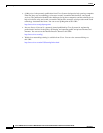
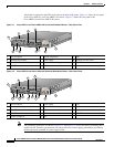
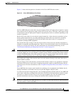
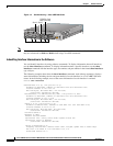
Figure 1-3 shows the front panel for all models of the Cisco uBR7100 series routers.
Figure 1-3 Cisco uBR7100 Series Front Panel
All Cisco uBR7100 series routers have one power supply with one AC-input power receptacle. A power
cable connects the AC-input power supply to the site AC power source. The router’s main power switch
is located next to the AC-input power receptacle. Separate power cords are available, depending on the
country of operation.
On the side of each chassis are two chassis ground receptacles—choose the most convenient set for a
chassis ground connection for a two-hole grounding lug, and the other set can provide a mounting
location for the cable management bracket. On the back of the chassis, there is a receptacle for
electrostatic discharge (ESD) equipment.
Four internal fans draw cooling air into the chassis (back to front) and across internal components to
maintain an acceptable operating temperature. There are four environmental sensors for monitoring the
cooling air as it leaves the chassis. For more information on environmental monitoring, see the
“Environmental Monitoring and Reporting Functions” section on page 6-2.
Caution To ensure the proper flow of cooling air across the internal components, a port adapter must be installed
in the port adapter slot. If no port adapter is installed, install a blank port adapter (the product number
is MAS-7100-PABLANK=). Slot 5 has a blank face plate. For proper airflow, make sure that a blank
faceplate is always installed in slot 5. (The product number is SM-BLANK=).
The modular port adapter slides into the chassis slot and connects directly to the router; there are no
internal cables to connect.
The port adapter, fixed cable interface, and fixed LAN interface connect to two peripheral component
interconnect (PCI) buses on the router’s backplane that provide a path to packet I/O memory and the
system processor. For more information, see the “Peripheral Component Interconnect Buses” section on
page 1-14.
Cisco uBR7100 series routers can be installed on a tabletop or in an equipment rack. Rubber feet for
tabletop installation are included in the accessory kit that shipped with your router.
A rack-mount and cable-management kit is also standard equipment included with all Cisco uBR7100
series routers when they are shipped from the factory. The kit provides the hardware needed to mount
the router in a standard 19-inch, four-post or telco-type equipment rack. The rack-mount kit also
provides the hardware necessary to manage the interface cables attached to the router.
Note Hardware to install the Cisco uBR7100 series in a 23-inch or 24-inch rack can also be ordered separately
(the order number is ACS-7100-RMK=).
37637
Cisco uBR7100
SERIES