


6-12
Cisco uBR7100 Series and Cisco uBR7100E Series Universal Broadband Router Hardware Installation Guide
OL-5916-01
Chapter 6 Maintenance
Upgrading the SDRAM Memory Modules
Warning
When installing or replacing the unit, the ground connection must always be made first and
disconnected last.
Statement 1046
Removing the Chassis Cover
To remove the top cover, use the following procedure:
Step 1 Make sure that you are properly grounded.
Step 2 Remove all power from the chassis.
Step 3 Remove all the network connections.
Step 4 Remove the chassis from the rack (if necessary) and place the it on a tabletop or workbench.
Caution If you are moving the chassis to a workbench or other work area, it is a good idea to reconnect the chassis
ground to help prevent ESD damage to the chassis components.
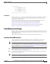
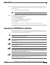
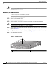
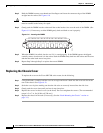
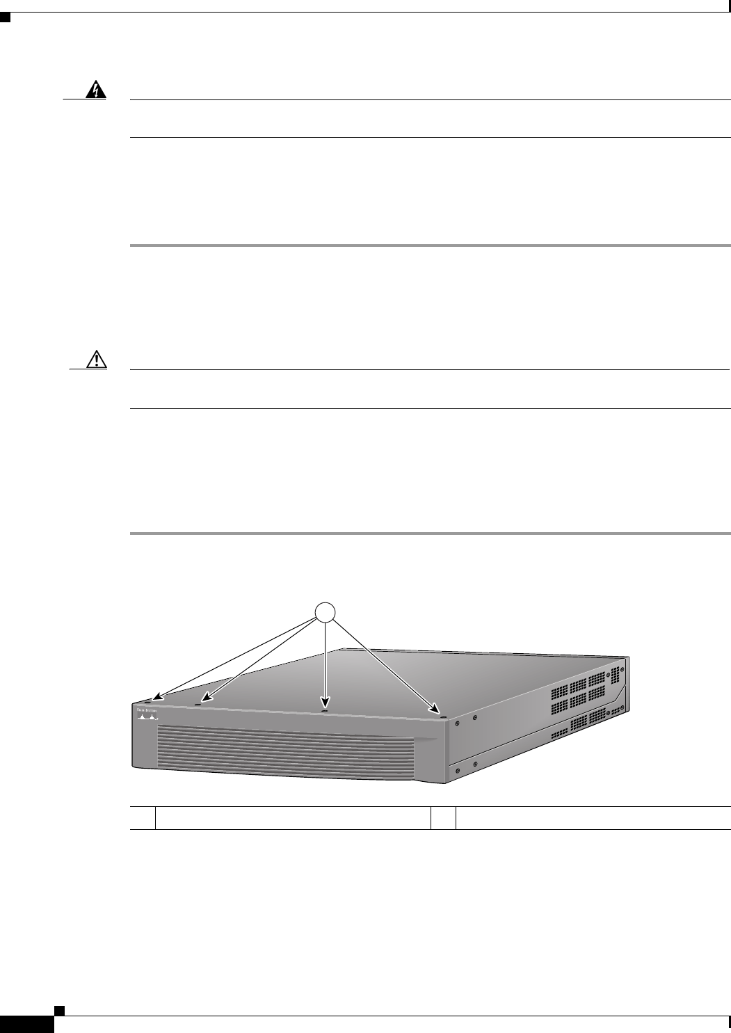
Step 5 Unscrew the four cover screws at the front of the chassis and place the screws in a safe, easily accessible
location. See Figure 6-5.
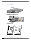
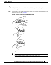
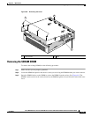
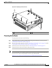
Step 6 Using both hands (one on either side of the cover), lift up the front of the cover and pull it towards you
until it is clear of the bezel at the rear of the chassis. See Figure 6-7.
Step 7 Place the cover in a safe location.
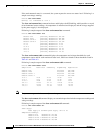
Figure 6-5 Locating the Screw
1 Cover screws
116839
Cisco uBR7100
SERIES
1