


5-2
Cisco uBR7100 Series and Cisco uBR7100E Series Universal Broadband Router Hardware Installation Guide
OL-5916-01
Chapter 5 Troubleshooting the Installation
Troubleshooting Overview
Locating the Serial Number on Your Router
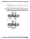
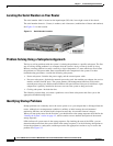
The serial number label is located on the input/output (I/O) side, lower-right corner of the chassis.
The serial number format is: 3 letters, 4 numbers, and 4 characters (combination of letters and numbers)
See Figure 5-1 for the location.
Figure 5-1 Serial Number Location
Problem Solving Using a Subsystems Approach
The key to solving problems with the system is isolating the problem to a specific subsystem. The first
step in solving startup problems is to compare what the system is doing to what it should be doing.
Because a startup problem is usually caused by a single component, it is more efficient to first isolate
the problem to a subsystem rather than to troubleshoot each component in the system. For these
troubleshooting procedures, consider the following subsystems:
• Power subsystem—Includes the power supply and the external power cable.
• Processor subsystem—Includes the network processing card, the modular port adapter, the service
module, and the fixed RF ports. The system memory and management functions reside on the
network processing card, and the enabled LED on each port indicates if the port is initialized. A port
adapter that is partially installed in the router can cause the system to hang and crash.
• Cooling subsystem—Includes the fans.
The following sections help you isolate a problem to one of these subsystems and direct you to the
appropriate troubleshooting section.
Identifying Startup Problems
Startup problems are commonly due to the source power or to a port adapter that is dislodged from the
router. Although an overtemperature condition is unlikely at initial startup, the environmental
monitoring functions are included in this chapter because they also monitor internal voltages.
When you start up the router for the first time, you should observe the startup sequence described in the
“Starting the System” section on page 4-2, which contains a more detailed description of the normal
startup sequence.
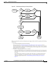
LEDs indicate all system states in the startup sequence. By checking the state of the LEDs, you can
determine when and where the system failed in the startup sequence. Use the following descriptions to
isolate the problem to a subsystem, and then proceed to the appropriate sections to try to resolve the
problem. See Figure 5-2.