


6-5
Cisco uBR7100 Series and Cisco uBR7100E Series Universal Broadband Router Hardware Installation Guide
OL-5916-01
Chapter 6 Maintenance
Flash Memory Card Usage
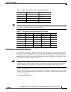
Voltage readings:
+2.5 V measured at +2.59 V
+3.3 V measured at +3.32 V
+5.15 V measured at +5.13 V
+12.3 V measured at +12.29 V
+12.3 V measured at +12.33 V
-12.5 V measured at -12.43 V
Envm stats saved 2 time(s) since reload
Fan Failures
When the system power is on, all four fans should be operational. The system continues to operate if a
fan fails; however, if the air temperature exceeds a defined threshold, the router displays warning
messages on the console terminal.
For complete descriptions and instructions of the environmental monitor commands, refer to the
Cisco IOS Configuration Fundamentals Configuration Guide at the following URL:
http://www.cisco.com/univercd/cc/td/doc/product/software/ios122/122cgcr/ffun_c/
and the Cisco IOS Configuration Fundamentals Command Reference at the following URL:
http://www.cisco.com/univercd/cc/td/doc/product/software/ios122/122cgcr/ffun_r/
Flash Memory Card Usage
The Cisco uBR7100 series router has two Personal Computer Memory Card International Association
(PCMCIA) slots for Type II flash memory cards. Slot 0 is the lower PCMCIA card slot and slot 1 is the
upper PCMCIA card slot.
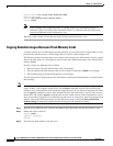
The following sections describe how to insert, remove, and format a flash memory card
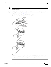
Inserting a Flash Memory Card
To insert a flash memory card in either PCMCIA slot of the Cisco uBR7100 series router, use the
following procedure. You do not need to power off the system to insert a flash memory card.
Note To avoid potential problems when inserting spare flash memory cards in your Cisco uBR7100 series
universal broadband router, we recommend that you reformat all of your flash memory cards during your
regularly scheduled service times. The “Formatting a Flash Memory Card” section on page 6-8 contains
instructions that explain how to reformat a flash memory card.
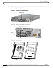
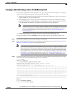
Step 1 Locate the PCMCIA card slots. For proper electrocmagnetic compliance (EMC), the slots have a cover
that is secured with a captive screw. (See Figure 6-1.)
Step 2 Use a flat-head screwdriver to loosen the captive screw that secures the protective cover, and lift the
protective cover. (See Figure 6-2.)
Tip The flash disk memory card slots are labelled slot 0 and slot 1 on the chassis, but the flash disk memory
cards themselves are addressed as disk0 and disk1, respectively, when using Cisco IOS commands.