


1-15
Cisco uBR7100 Series and Cisco uBR7100E Series Universal Broadband Router Hardware Installation Guide
OL-5916-01
Chapter 1 Product Overview
Functional Overview
Network Processor Card
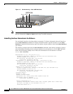
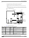
The network processor card resides inside the chassis and is shown in Figure 1-6 on page 1-16. The
network processor card provides the following features:
• Senses OIR of the port adapter
• Bridges the PCI buses from the interfaces to packet memory
• Arbitrates traffic across the PCI buses
• Generates the clock signals for the interfaces on each PCI bus
The network processor card also performs the following system management functions:
• Sending and receiving routing protocol updates
• Managing tables, caches, and buffers
• Monitoring interface and environmental status
• Providing Simple Network Management Protocol (SNMP) management and the console or Telnet
interface
• Accounting and switching of data traffic
• Booting and reloading images
• Managing port adapters (recognition and initialization during OIR)
Note For instructions for removing and replacing memory components on the network processor card, such
as the SDRAM DIMMs, refer to Memory Replacement Instructions for the Network Processing Engine
or Network Services Engine and Input/Output Controller at the following URL:
http://www.cisco.com/univercd/cc/td/doc/product/core/7206/fru/memory/index.htm
The network processor card consists of the following components:
• Reduced Instruction Set Computing (RISC) microprocessor running at 175 MHz
• Two system controllers—Provide processor access to two separate banks of SDRAM and permit
devices on both PCI buses to access either SDRAM bank. This means that devices on different PCI
buses can access different SDRAM banks simultaneously.
• Upgradable memory modules—SDRAM system memory defaults to 128 MB and can be upgraded
to either 192 MB or 256 MB. (SDRAM packet memory is fixed at 64 MB.) SDRAM memory stores
packets received or sent from network interfaces, routing tables, and network accounting
applications. The two independent SDRAM memory arrays allow concurrent access by interfaces
and the processor. For information about accessing the SDRAM memory modules, refer to the
“Upgrading the SDRAM Memory Modules” section on page 6-11.
Note The network processor card contains two SDRAM slots for user-configurable system memory, DIMM 1
and DIMM 2. The amount of memory installed in slot DIMM 1 must be greater than or equal to the
memory installed in slot DIMM 2. Slot DIMM 2 is zero for the default memory configuration of
128 MB. Slot DIMM 0 is used only for packet memory and is fixed at 64 MB in the factory.
• Cache memory—Cisco uBR7100 series routers have two levels of cache: a primary cache that is
internal to the microprocessor and a secondary, 2-MB (fixed) external cache that provides additional
high-speed storage for data and instructions.