


3-5
Cisco uBR7100 Series and Cisco uBR7100E Series Universal Broadband Router Hardware Installation Guide
OL-5916-01
Chapter 3 Installing Cisco uBR7100 Series Universal Broadband Routers
Attaching the System Ground Connection
Attaching the System Ground Connection
Warning
When installing or replacing the unit, the ground connection must always be made first and
disconnected last.
Statement 1046
Before you connect power or turn on power to your router, we strongly recommend that you provide an
adequate chassis ground (earth) connection for your router’s chassis. This connection is required for a
central office that must comply with Telcordia bonding requirements; it is optional but highly
recommended for other installations.
Note The Telcordia bonding connections are in addition to the grounding that is required for the AC power
connection.
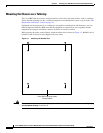
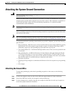
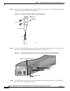
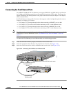
Chassis grounding receptacles for Telcordia bonding connections are provided on each side of the router,
near the rear of the chassis.
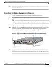
Note One set of grounding receptacles should be used for the Telcordia bonding ground connection, and the
other set can be used for attaching the cable management bracket (see Attaching the Ground Wire).
To ensure that the chassis grounding connection that you provide is adequate, you need the following
parts and tools:
• One grounding lug—Must have two 3.5-mm screw holes that have a 0.63-inch (16.002-mm) spacing
between them, and a wire receptacle large enough to accept a 6-American Wire Gauge (AWG)
multistrand, copper wire. This grounding lug is provided in the accessory kit.
• Two slotted hexhead 3.5 x 7-mm thread-forming machine screws. These screws are provided in the
accessory kit.
• One grounding wire—6-AWG, 0.162-inch (4.115-mm) diameter, with approximately 0.108 inch
(2.743 mm) of insulation, for a total wire diameter of approximately 0.27 inch (6.858 mm). The
wire’s length is dependent on your router location and site environment. This wire is not available
from Cisco Systems; it is available from any commercial cable vendor.
• Flat-blade screwdriver
• Crimping tool large enough to accommodate the diameter of the wire receptacle on your grounding
lug
• Wire stripper
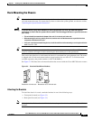
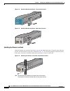
Attaching the Ground Wire
To attach the grounding lug to the chassis grounding receptacles on the router, use the following
procedure:
Step 1 Use the wire stripper to strip one end of the 6-AWG wire approximately 0.75 inch (19.05 mm).
Step 2 Insert the 6-AWG wire into the wire receptacle on the grounding lug.
Step 3 Use the crimping tool to carefully crimp the wire receptacle around the wire; this step is required to
ensure that a proper mechanical connection.