


6-16
Cisco uBR7100 Series and Cisco uBR7100E Series Universal Broadband Router Hardware Installation Guide
OL-5916-01
Chapter 6 Maintenance
Upgrading the SDRAM Memory Modules
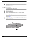
Step 3 Hold the DIMM between your thumbs and forefingers and insert the connector edge of the DIMM
straight into the socket. See Figure 6-10.
Caution When inserting the DIMM, use firm but not excessive pressure. If the socket is damaged, the chassis
must be returned to the factory for repair.
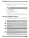
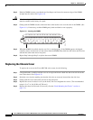
Step 4 Gently push the DIMM into the socket until the socket latches close over the ends of the DIMM. (See
Figure 6-11.) If necessary, rock the DIMM gently back and forth to seat it properly.
Figure 6-11 Inserting the DIMM
Step 5 When the DIMM is installed, check to see if it is seated properly. If the DIMM appears misaligned,
carefully remove it and reseat it in the socket. Push the DIMM firmly back into the socket until first one
and then the other latch moves into place.
Step 6 Repeat Step 2 through Step 5 to replace the second DIMM.
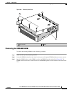
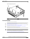
Replacing the Chassis Cover
To replace the cover on the Cisco uBR7100 series router, do the following:
Step 1 Using both hands, carefully hold the cover at an angle and insert it back into the cover tab slots at the
rear of the chassis. See Figure 6-12.
Step 2 Settle the cover in place making sure that the side tabs are correctly inserted into the side slots.
Step 3 Gently push the cover down until you hear it snap into place.
Step 4 Replace the screws in chassis cover (at the front). Do not overtighten the screws. (The recommended
torque is 5 to 7 in. lbs [0.564 to 0.790 nm].)
Step 5 Replace the chassis in the rack (if necessary). See the “Rack-Mounting the Chassis” section on
page 3-3.)
13418