


3-11
Cisco uBR7100 Series and Cisco uBR7100E Series Universal Broadband Router Hardware Installation Guide
OL-5916-01
Chapter 3 Installing Cisco uBR7100 Series Universal Broadband Routers
Connecting the Console Port and Auxiliary Port
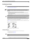
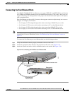
Step 3 Attach the DB-9 connector to the appropriate serial connector on the PC or terminal. (See Figure 3-11.)
Step 4 Configure the terminal or PC terminal emulation software for 9600 baud, 8 data bits, no parity, 2 stop
bits, and no flow control.
Note Do not set the terminal emulation software for either hardware or software flow control. Doing
so will prevent communications with the router.
Connecting a Modem to the Auxiliary Port
You can use the auxiliary port to connect a terminal or a modem for remote access to the router.
Note For more information about the console port and auxiliary port connectors, see the “Console and
Auxiliary Port Cables and Pinouts” section on page C-2.
To connect the auxiliary port to a modem, use the following procedure:
Step 1 Connect one end of the RJ-45 rollover cable to the RJ-45-to-DB-25 adapter (labeled MODEM).
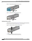
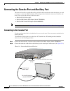
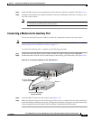
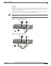
Step 2 Connect the other end of the rollover cable directly to the auxiliary port on the router. (See Figure 3-12.)
Figure 3-12 Connecting a Modem to the Auxiliary Port
Step 3
Attach the DB-25 connector to the modem. (See Figure 3-12.)
Step 4 Make sure that the modem and the auxiliary port on the router are configured for the same transmission
speed (38.4 Kbps and 56 Kbps are typical). Configure the modem for auto-answer, and for hardware flow
control using the Data Carrier Detect (DCD) and Data Terminal Ready (DTR) signals.
5
I
ACT
ACT
LNK
1
PWR
SL
O
T
0
S
LO
T
1
PWR
SYS
RDY
DS0
RF
uBR7114
US0
E
N
DS0
US1
US2
US3
CONS
AUX
FE 0/1
FE 0/0
35828
RJ-45-to-RJ-45
rollover cable
Auxiliary port
(RJ-45)
Modem
RJ-45-to-DB-25 adapter
(labeled MODEM)