


3-12
Cisco uBR7100 Series and Cisco uBR7100E Series Universal Broadband Router Hardware Installation Guide
OL-5916-01
Chapter 3 Installing Cisco uBR7100 Series Universal Broadband Routers
Connecting the Power
Connecting the Power
Cisco uBR7100 series routers feature four-output switching AC power supplies that provide power
factor correction and regulated outputs. Cisco uBR7100 series routers have one AC-input power supply.
Note For information on the power supply specifications, see Appendix A, “System Specifications”.
Warning
Do not touch the power supply when the power cord is connected. For systems with a power switch,
line voltages are present within the power supply even when the power switch is off and the power
cord is connected. For systems without a power switch, line voltages are present within the power
supply when the power cord is connected.
Statement 4
Check the following conditions before you start the router:
• The port adapter is securely inserted in its slot.
• All network interface cables are connected.
• A flash disk or flash memory card is installed in its PC Card slot.
• The console terminal is connected and powered on.
To connect the AC power on Cisco uBR7100 series routers, use the following procedure:
Step 1 At the back of the router, check that the power switch is in the OFF (O) position.
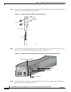
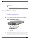
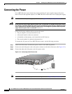
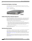
Step 2 Connect one end of the power cord to the power connector on the back of the router. (See Figure 3-13.)
Step 3 Connect the other end of the power cord to the power outlet.
Figure 3-13 Connecting the AC Power Cord
Note For information on system startup and software configuration, see Chapter 4, “System Startup.”
5
I
ACT
ACT
LNK
1
PWR
S
L
O
T
0
S
LO
T
1
PWR
SYS
RDY
DS0
RF
uBR7114
US0
E
N
DS0
US1
US2
US3
CONS AUX
FE 0/1
FE 0/0
35829