


1-18
Cisco uBR7100 Series and Cisco uBR7100E Series Universal Broadband Router Hardware Installation Guide
OL-5916-01
Chapter 1 Product Overview
Functional Overview
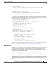
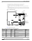
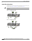
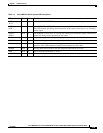
System LEDs and Reset Button
The LEDs indicate the status of the router. The CPU reset button allows you to reset the entire system.
The LEDs are shown in Figure 1-7 and Figure 1-8, and are described in Table 1-5.
Caution To prevent system errors and problems, use the CPU reset button only at the direction of your service
representative.
Figure 1-7 Cisco uBR7111 System LEDS
Figure 1-8 Cisco uBR7114 System LEDs
5
I
ACT
ACT
LNK
1
PWR
S
LO
T 0
S
LO
T
1
PWR
SYS
RDY
DS0
RF
uBR7114
US0
E
N
DS0
CONS AUX
FE 0/1
FE 0/0
Active
DS0 RF
DS0
Link
Power
Sys Rdy
Card Enable
U0 Enable
Link
Active
DS0
US0
EN
PWR
SYS
RDY
RF
ACT ACT
LNK
2
LNK
1
37403
5
I
ACT
ACT
LNK
1
PWR
SL
O
T
0
S
LO
T
1
PWR
SYS
RDY
DS0
RF
uBR7114
US0
E
N
DS0
US1
US2
US3
CONS AUX
FE 0/1
FE 0/0
Active
DS0 RF
U2 Enable
U3 Enable
DS0
Link
Power
Sys Rdy
Card Enable
U0 Enable
U1 Enable
Link
Active
DS0
US3
US2 US1
US0
EN
PWR
SYS
RDY
RF
ACT ACT
LNK
2
LNK
1
36455