


4-3
Cisco uBR7100 Series and Cisco uBR7100E Series Universal Broadband Router Hardware Installation Guide
OL-5916-01
Chapter 4 System Startup
Starting the System
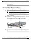
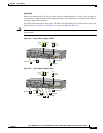
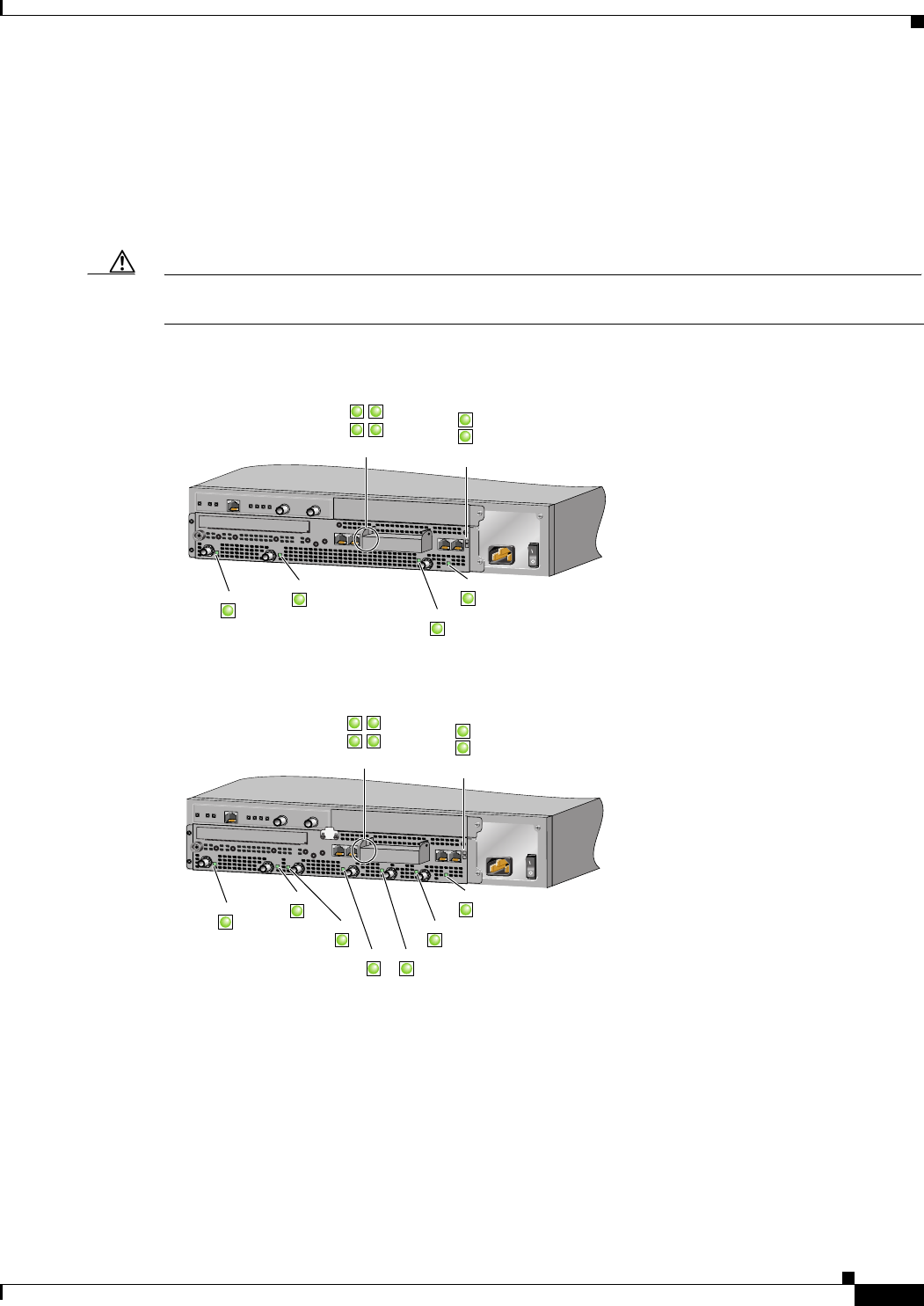
System LEDs
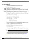
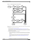
Many of the interface LEDs do not go on until you have configured them. To verify correct operation of
each interface, complete the first-time startup procedures and configuration, and then use the LEDs to
check the status of the interfaces.
The LEDs indicate the status of the router. The CPU reset button that you to reset the entire system. The
LEDs are shown in Figure 4-1 and Figure 4-2, and are described in Table 4-1.
Caution To prevent system errors and problems, use the CPU reset button only at the direction of your service
representative.
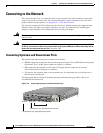
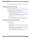
Figure 4-1 Cisco uBR7111 System LEDS
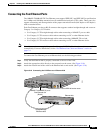
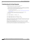
Figure 4-2 Cisco uBR7114 System LEDs
5
I
ACT
ACT
LNK
1
PWR
SLO
T
0
S
LO
T 1
PWR
SYS
RDY
DS0
RF
uBR7114
US0
E
N
DS0
CONS AUX
FE 0/1
FE 0/0
Active
DS0 RF
DS0
Link
Power
Sys Rdy
Card Enable
U0 Enable
Link
Active
DS0
US0
EN
PWR
SYS
RDY
RF
ACT ACT
LNK
2
LNK
1
37403
5
I
ACT
ACT
LNK
1
PWR
S
L
O
T
0
SLO
T
1
PWR
SYS
RDY
DS0
RF
uBR7114
US0
E
N
DS0
US1
US2
US3
CONS AUX
FE 0/1
FE 0/0
Active
DS0 RF
U2 Enable
U3 Enable
DS0
Link
Power
Sys Rdy
Card Enable
U0 Enable
U1 Enable
Link
Active
DS0
US3
US2 US1
US0
EN
PWR
SYS
RDY
RF
ACT ACT
LNK
2
LNK
1
36455