


1-11
Cisco uBR7100 Series and Cisco uBR7100E Series Universal Broadband Router Hardware Installation Guide
OL-5916-01
Chapter 1 Product Overview
Functional Overview
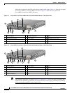
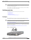
Rack-Mount and Cable-Management Kit
The rack-mount and cable-management kit for Cisco uBR7100 series routers consists of rack-mount
brackets and a cable-management bracket that are designed for mounting your router in 19-inch,
four-post or telco-type equipment racks. The kit is shipped with each Cisco uBR7100 series router and
is also available as a single FRU.
Note Rubber feet for tabletop installation are included in the accessory kit that shipped with your router.
Hardware for mounting the router in a 23- or 24-inch rack is available separately. The product number
for this kit is ACS-7100-RMK=.
For detailed instructions about how to install the rack-mount and cable-management brackets on your
Cisco uBR7100 series router, see the “Attaching the Cable-Management Bracket” section on page 3-7.
Functional Overview
The following sections provide a functional overview of Cisco uBR7100 series routers to help you
become familiar with the capabilities of the router:
• Chassis Slot and Logical Interface Numbering, page 1-11
• Online Insertion and Removal, page 1-14
• Peripheral Component Interconnect Buses, page 1-14
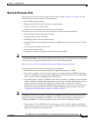
• Network Processor Card, page 1-15
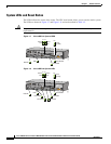
• System LEDs and Reset Button, page 1-18
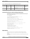
Chassis Slot and Logical Interface Numbering
In Cisco uBR7100 series routers, the slot number is the location in the chassis where the interface resides
and the port number is the physical port associated with that slot. Cisco uBR7100 series router slots are
numbered 0 through 5. Interfaces in the Cisco IOS software are identified by a type, slot number, and
port number. The number of physical ports depends on the type of modular port adapter or fixed
interface. For example, Fast Ethernet 0/1 indicates port 1 on the fixed LAN interface in slot 0.
Slots in the Cisco uBR7100 series are numbered as follows:
• Slot 0—Fixed LAN (Fast Ethernet) interface
• Slot 1—Fixed RF interface
• Slot 3—Modular port adapter
Note Slots 2, 4, and 5 are not used on the Cisco uBR7100 series router.
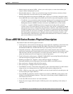
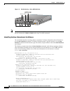
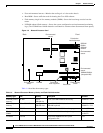
Figure 1-5 illustrates the slot placement on Cisco uBR7114 and Cisco uBR7114E routers. The
placement on the Cisco uBR7111 and Cisco uBR7111E routers is identical.