


1-4
Cisco uBR7100 Series and Cisco uBR7100E Series Universal Broadband Router Hardware Installation Guide
OL-5916-01
Chapter 1 Product Overview
Cisco uBR7100 Series Routers Physical Description
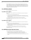
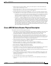
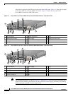
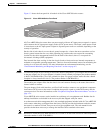
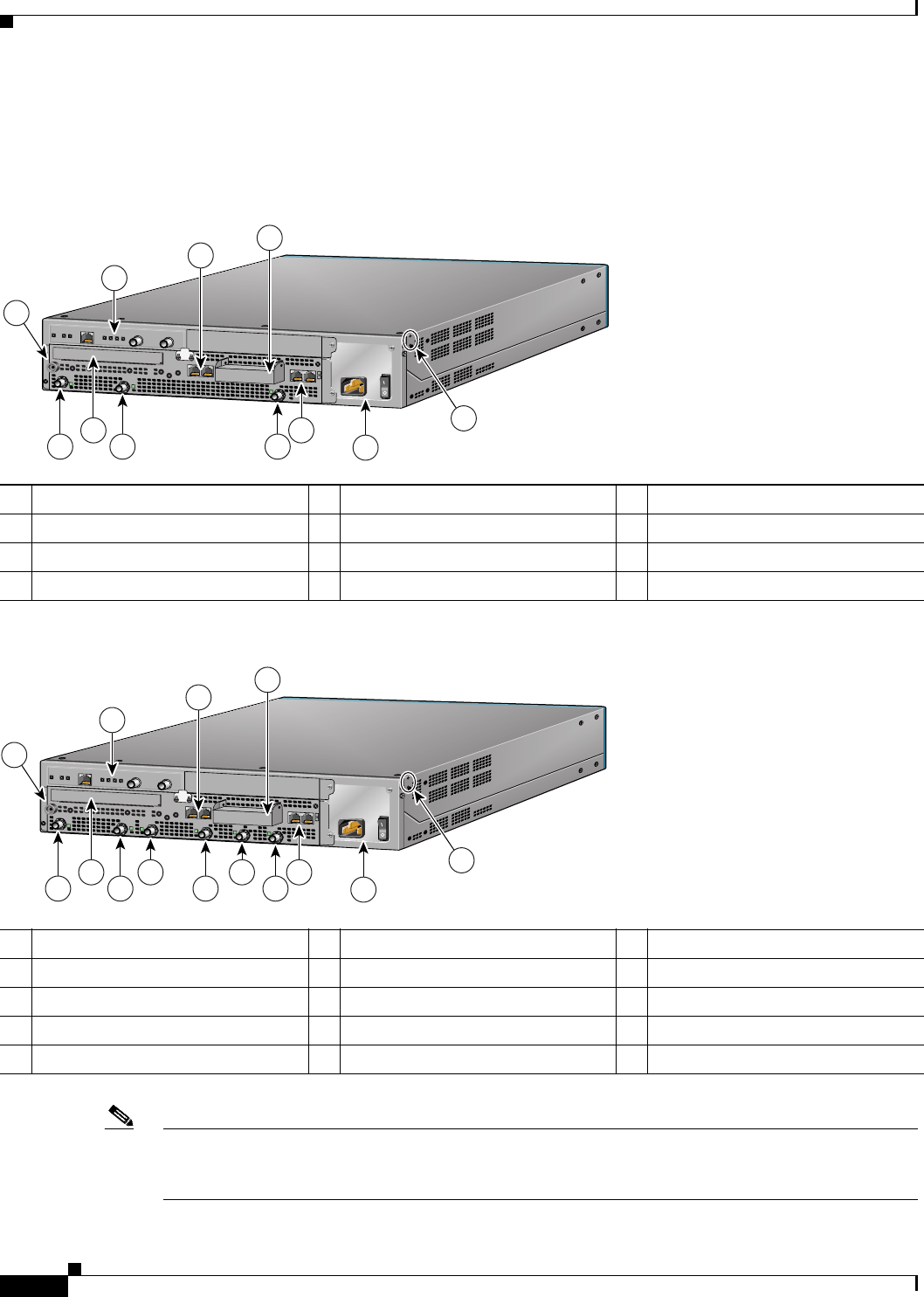
All interface connections and LEDs are located at the back of the router. Figure 1-1 shows the rear panel
of the Cisco uBR7111 and Cisco uBR7111E routers. Figure 1-2 shows the rear panel of the
Cisco uBR7114 and Cisco uBR7114E routers.
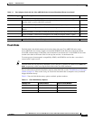
Figure 1-1 Cisco uBR7111 and Cisco uBR7111E Universal Broadband Router—Rear Panel View
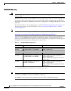
Figure 1-2 Cisco uBR7114 and Cisco uBR7114E Universal Broadband Router—Rear Panel View
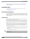
Note The grounding receptacles are shown in Figure 1-1 and Figure 1-2 are for the chassis grounding that is
required by the Telcordia specifications for central office use. Power supply grounding is provided by
the three-pronged grounded AC power supply outlet.
1 ESD receptacle 5 Ground receptacles 9 DS0
2 Modular port adapter 6 Power supply 10 Module slot (not used)
3 Fixed Fast Ethernet LAN ports 7 Console and auxiliary ports 11 DS0 RF
4 PCMCIA card slots (covered) 8 US0
1 ESD receptacle 6 Power supply 11 US3
2 Modular port adapter 7 Console and auxiliary ports 12 DS0
3 Fixed Fast Ethernet LAN ports 8 US0 13 Module slot (not used)
4 PCMCIA card slots (covered) 9 US1 14 DS0 RF
5 Ground receptacle 10 US2
5
I
ACT
ACT
LNK
1
PWR
S
LO
T
0
S
LO
T
1
PWR
SYS
RDY
DS0
RF
uBR7114
US0
E
N
DS0
CONS AUX
FE 0/1
FE 0/0
116834
5
1
2
7
8
6
9
10
11
3
4
5
I
ACT
ACT
LNK
1
PWR
S
LO
T
0
S
LO
T
1
PWR
SYS
RDY
DS0
RF
uBR7114
US0
E
N
DS0
US1
US2
US3
CONS AUX
FE 0/1
FE 0/0
116835
5
1
2
7
8
9
6
12
11
10
13
14
3
4