


5-32 Chapter 5, Error Messages and Codes
Addendum 108431-001 (11-88) to
Manual No. 108033-003
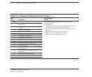
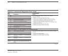
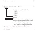
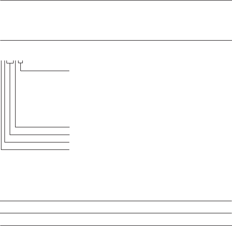
Memory error codes in the following tables are in the format:
Xx000Y ZZ 201
Failed data bit. Values are: 00, 01, 02, 04, 08, 10, 20, 40, 80.
00 = parity bit
01 = data bit 0
02 = data bit 1
04 = data bit 2
08 = data bit 3
10 = data bit 4
20 = data bit 5
40 = data bit 6
80 = data bit 7
Failed byte. Values are 0, 1, 2, 3.
Always zero.
Ignore.
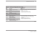
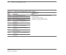
Failed address. Values are 0 through F. They indicate soldered memory
or socketed memory and whether the board is the 32-bit system memory
board, the 1- to 2-megabyte 32-bit memory board, or the 4- to 8-mega-
byte 32-bit memory board.
0 or F* = soldered on the 32-bit system memory board
1 = socketed on the 32-bit system memory board
2* = soldered on the 1- to 2-megabyte 32-bit memory board
3 = socketed on the 1- to 2-megabyte 32-bit memory board
2 thru 5* = soldered on the 4- to 8-megabyte 32-bit memory board
6 thru 9 = socketed on the 4- to 8-megabyte 32-bit memory board
* If error indicates a soldered chip), replace the board.
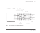
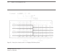
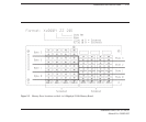
After identifying X, use Figures 5-1, 5-2, and 5-3 to identify the location of the bad data bit.