


Maintenance and Service Guide 7-29
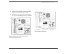
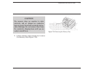
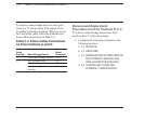
2. Be sure that all the pins are in the socket
and that none are bent.
3. Press the chip into place.
4. Complete the replacement procedures in
the following sections:
a. 7.12 MEMORY EXPANSION BOARD(S).
If applicable.
b. 7.10 EXPANSION BOARD(S).
c. 7.6 SYSTEM UNIT COVER AND
INTERNAL CONFIGURATION
d. 7.5 PREPARING THE SYSTEM UNIT
FOR THE INTERNAL REMOVAL
AND REPLACEMENT PROCEDURES
e. 7.3 KEYBOARD
f. 7.2 MONITOR
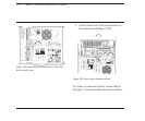
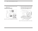
7.14 SPEAKER ASSEMBLY AND
SECURITY LOCK SWITCH
The security lock switch and the speaker assem-
bly are inside the speaker/board guide assembly,
which is accessible for removal only by removing
all the expansion boards in the system unit.
To remove the speaker assembly or security lock
switch, follow these steps:
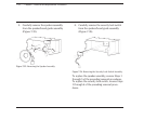
1. Complete the removal procedures in the
following sections:
a. 7.2 MONITOR
b. 7.3 KEYBOARD
c. 7.5 PREPARING THE SYSTEM UNIT
FOR THE INTERNAL REMOVAL
AND REPLACEMENT PROCEDURES
d. 7.6 SYSTEM UNIT COVER AND
INTERNAL CONFIGURATION
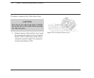
e. 7.10 EXPANSION BOARD(S). Remove
only the expansion boards that block
the speaker/board guide assembly.