7-24 Chapter 7, Removal and Replacement Procedures
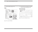
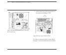
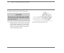
To replace the 80287 coprocessor, follow
these steps:
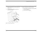
1. Align the pins on the 80287 coprocessor
with the 80287 coprocessor socket.
2. Press the coprocessor into the socket.
3. Complete the replacement procedures in
the following sections:
a. 7.10 EXPANSION BOARD(S). Remove
expansion boards in slots 1, 2, and 3.
b. 7.6 SYSTEM UNIT COVER AND
INTERNAL CONFIGURATION
c. 7.5 PREPARING THE SYSTEM UNIT
FOR THE INTERNAL REMOVAL
AND REPLACEMENT PROCEDURES
d. 7.3 KEYBOARD
e. 7.2 MONITOR
7.12 MEMORY EXPANSION
BOARD(S)
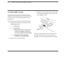
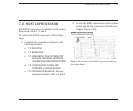
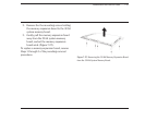
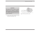
The 1- to 2-megabyte or the 4- to 8-megabyte
memory expansion board is secured to the 32-bit
system memory board by two connectors and
five Phillips head mounting screws.
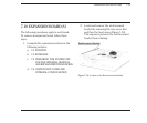
To remove a memory expansion board, follow
these steps:
1. Complete the removal procedures in the
following sections:
a. 7.2 MONITOR
b. 7.3 KEYBOARD
c. 7.5 PREPARING THE SYSTEM UNIT
FOR THE INTERNAL REMOVAL
AND REPLACEMENT PROCEDURES
d. 7.6 SYSTEM UNIT COVER AND
INTERNAL CONFIGURATION
e. 7.10 EXPANSION BOARD(S). Remove
only the 32-bit system memory
board.


