7-54 Chapter 7, Removal and Replacement Procedures
Addendum 108431-001 (11-88) to
Manual No. 108033-003
Power Supply
To remove the power supply from the expansion
unit complete the following steps.
1. Complete the steps at the beginning of
this section.
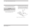
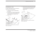
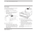
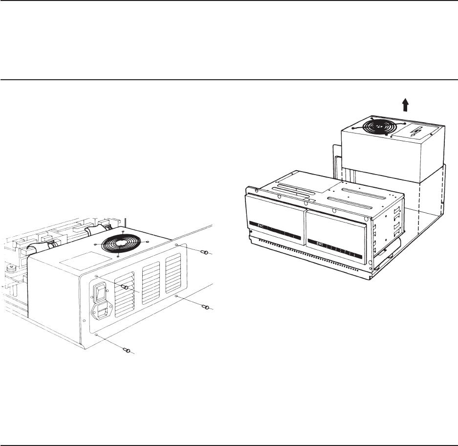
2. Remove the four screws securing the power
supply assembly to the expansion unit
chassis (Figure 7-54).
Figure 7-54. Power Supply Screws.
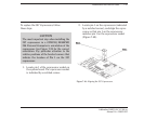
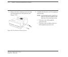
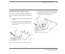
3. Slide the power supply ½-inch to 1-inch
toward the drive housing (Figure 7-55). Be
sure to clear the tabs on the bottom of the
chassis. These tabs hold the power supply
assembly in place.
Figure 7-55. Removing the Power Supply Assembly.
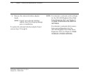
4. Shift the power supply away from the ex-
ternal interface adapter board to access the
connector on the board.
5. Disconnect the power supply connector
from the external interface adapter board
and lift the power supply assembly out of
the chassis.
To replace the power supply assembly, reverse
steps 1 through 5.


