


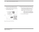

7-48 Chapter 7, Removal and Replacement Procedures
Addendum 108431-001 (11-88) to
Manual No. 108033-003
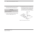
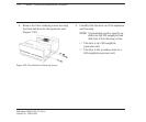
CAUTION
More pressure is needed to press the copro-
cessor into the socket than is required for
installing memory chips. BE SURE the pres-
sure exerted is firm enough to seat the
coprocessor and is applied evenly over the
surface of the coprocessor.
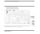
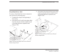
3. Press the coprocessor into the coprocessor
socket.
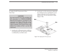
NOTE: If you think the coprocessor is not
seated properly, use the coproces-
sor removal tool to remove the
coprocessor, and try again to
install it.
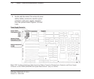
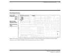
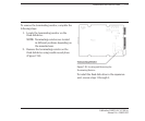
4. Verify DIP switch settings.
5. Complete the replacement procedures in
the following sections:
a. 7.16 SYSTEM BOARD. Be sure to tighten
the mounting screws because they
provide proper grounding for the
system.
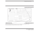
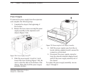
NOTE: When you reconnect the power
cables, refer to the configuration
label on the drive housing assembly
for the location of the connectors.
b. 7.14 SPEAKER ASSEMBLY AND
SECURITY LOCK SWITCH.
c. 7.10 EXPANSION BOARD(S).
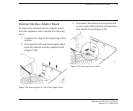
d. 7.6 SYSTEM UNIT COVER AND
INTERNAL CONFIGURATION
e. 7.5 PREPARING THE SYSTEM UNIT
FOR THE INTERNAL REMOVAL
AND REPLACEMENT
PROCEDURES
f. 7.3 KEYBOARD
g. 7.2 MONITOR
6. Run the SETUP program.