8-106 Dell PowerEdge 2100/180 and 2100/200 Systems User’s Guide
The diskette drive interface cable (Figure 8-8) provides an
interface between the standard diskette drive in the top bay
and the computer’s built-in diskette controller. The connec-
tors on the cable are identical; however, the ends of the cable
are labeled CNTL for the diskette controller connector
(FLOPPY) and DRIVE for the diskette drive connector. (To
identify the FLOPPY connector, see Figure 7-1.)
Figure 8-8. Diskette Drive Interface Cable
Installing Diskette Drives That Use the
Diskette Drive Controller
To install a 5.25- or 3.5-inch diskette drive that uses the
built-in diskette drive controller, follow these steps:
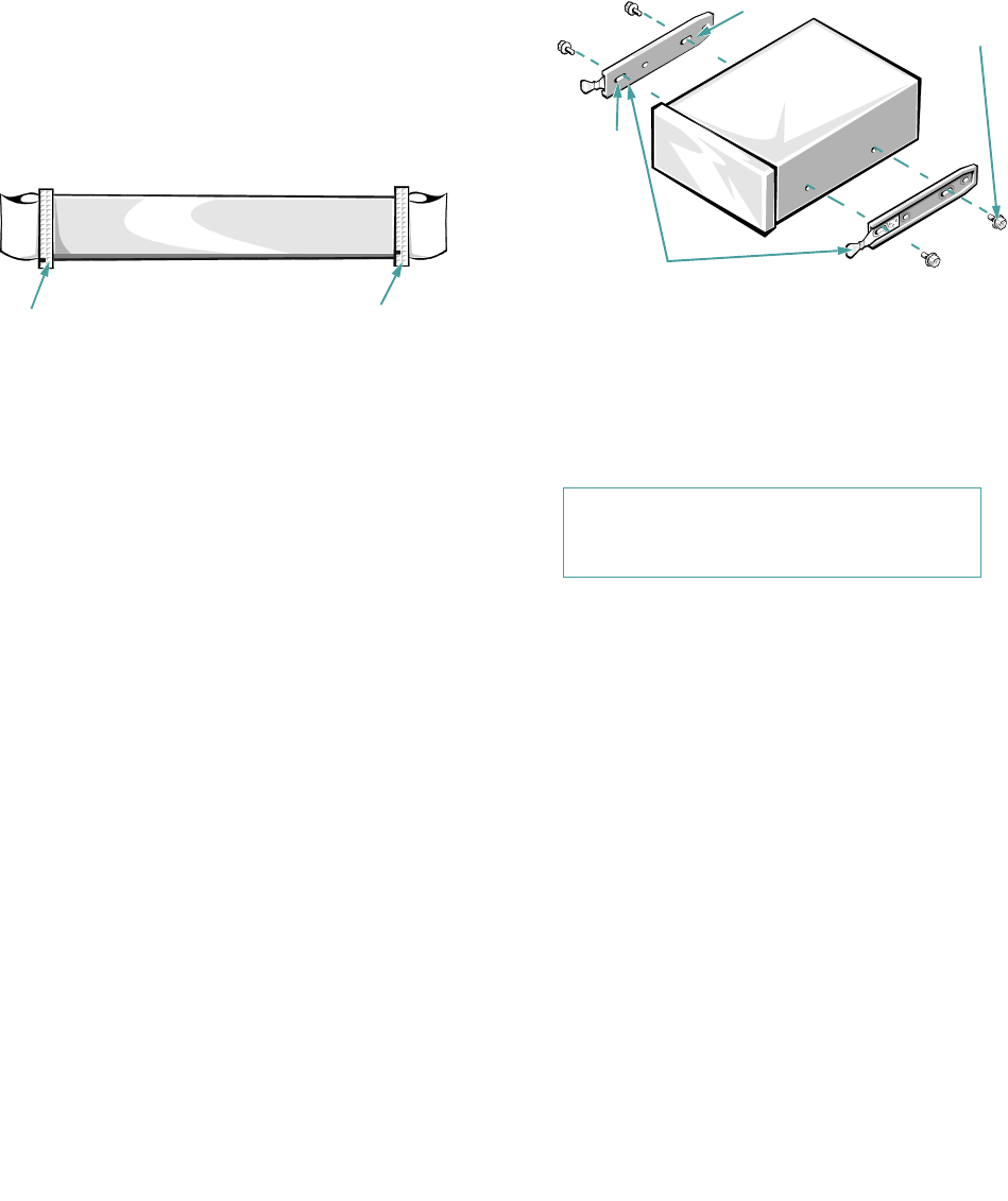
1. Prepare the drive for installation.
Ground yourself by touching an unpainted metal sur-
face on the back of the computer, unpack the drive,
and compare the jumper settings with those in the
drive documentation. Change any settings necessary
for your system’s configuration.
If the drive does not already have drive rails
attached, attach a drive rail to each side of the drive.
Orient the drive rails as shown in Figure 8-9. Secure
each drive rail to the drive with a screw in the first (from
the front) and third slotted screw holes on the drive rail
as shown in Figure 8-9.
Figure 8-9. Attaching Drive Rails
2. Remove the computer cover and front bezel
according to the instructions in “Removing the
Computer Cover” and “Removing the Front
Bezel” in Chapter 6.
3. Slide the new drive into its bay until it snaps
securely into place.
If necessary, you can adjust drive alignment by repo-
sitioning one or both rails.
4. Connect a DC power cable and the diskette inter-
face cable to the back of the drive (see Figure 8-1).
If other installed drives are in the way, you can tem-
porarily move them out of the way. Press in on the
plastic drive rails at the front of the bay to disengage
a drive; then slide the drive toward the front of the
chassis (see Figure 8-8).
Refer to Figure 8-6 to determine the appropriate DC
power cable connector to use, depending on the type of
drive. Plug the DC power cable into the 4-pin power
input connector on the back of the drive.
controller connector
drive connector
CAUTION: See “Protecting Against Elec-
trostatic Discharge” in the safety
instructions at the front of this guide.
first slot
mounting
screws (4)
rails (2)


