


B-124 Dell PowerEdge 2100/180 and 2100/200 Systems User’s Guide
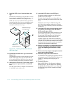
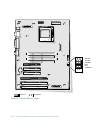
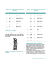
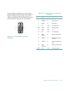
Connectors and Sockets
Table B-2 lists the connectors and sockets located on the
system board and gives a brief description of their
functions.
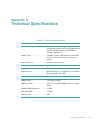
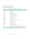
Table B-2. Connectors and Sockets on the System Board
Connector or Socket Description
AUXFAN Fan connector (reserved for an auxiliary fan)
BATTERY Battery connector
DIMM_x DIMM socket
EISAn EISA expansion-card connector
FAN Fan connector (microprocessor cooling fan)
FLOPPY Diskette controller connector
HDLED Hard-disk drive access indicator connector
JVGA Monitor connector
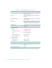
KYBD/MOUSE Keyboard and mouse connectors
PANEL Front-panel connector
PARALLEL Parallel port connector; sometimes referred to as LPT1
PCIn PCI expansion-card connector
POWER Power input connector
POWER3V Three-volt power input connector
PROCESSOR Microprocessor socket
SCSI Built-in SCSI controller connector
SERIAL Serial port connectors; sometimes referred to as COM1 and COM2
SVR_MGT Server management upgrade socket (reserved for future Dell server management
card)
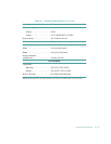
NOTE: For the full name of an abbreviation or acronym used in this table, see the Glossary.