


B-128 Dell PowerEdge 2100/180 and 2100/200 Systems User’s Guide
mouse detects the movement of a small ball and relays the
direction to the computer.
Mouse driver software can give the mouse priority with
the microprocessor by issuing IRQ12 whenever a new
mouse movement is made. The driver software also
passes along the mouse data to the application program
that is in control.
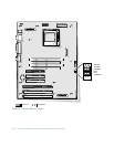
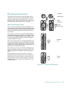
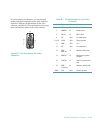
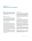
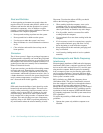
Keyboard Connector
If you reconfigure your hardware, you may need pin num-
ber and signal information for the keyboard connector.
Figure B-5 illustrates the pin numbers for the keyboard
connector, and Table B-5 lists and defines the pin assign-
ments and interface signals for the keyboard connector.
Figure B-5. Pin Numbers for the Keyboard
Connector
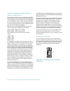
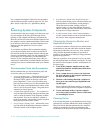
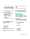
Mouse Connector
If you reconfigure your hardware, you may need pin
number and signal information for the mouse connector.
Figure B-6 illustrates the pin numbers for the mouse
connector, and Table B-6 lists and defines the pin assign-
ments and interface signals for the mouse connector.
Figure B-6. Pin Numbers for the Mouse
Connector
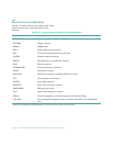
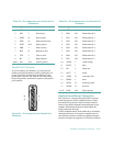
The system uses a 15-pin high-density D-subminiature
connector on the back panel for attaching a video graph-
ics array (VGA)-compatible monitor to your computer.
The video circuitry on the system board synchronizes the
signals that drive the red, green, and blue electron guns in
the monitor.
NOTE: Installing a video card automatically disables
the system’s built-in video subsystem.
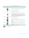
Table B-5. Pin Assignments for the Keyboard
Connector
Pin Signal I/O Definition
1 KBDATA I/O Keyboard data
2 NC N/A No connection
3 GND N/A Signal ground
4 FVcc N/A Fused supply voltage
5 KBCLK I/O Keyboard clock
6 NC N/A No connection
Shell N/A N/A Chassis ground
shell
6
4
3
2
1
5
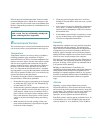
Table B-6. Pin Assignments for the Mouse
Connector
Pin Signal I/O Definition
1 MFDATA I/O Mouse data
2 NC N/A No connection
3 GND N/A Signal ground
4 FVcc N/A Fused supply voltage
5 MFCLK I/O Mouse clock
6 NC N/A No connection
5
3
1
2
4
6
shell