


Hardware Configuration Features B-127
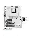
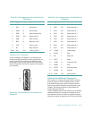
Parallel Port Connector
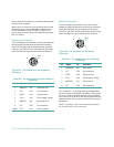
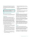
If you reconfigure your hardware, you may need pin
number and signal information for the parallel port con-
nector. Figure B-4 illustrates the pin numbers for the
parallel port connector, and Table B-4 lists and defines
the pin assignments and interface signals for the parallel
port connector.
Figure B-4. Pin Numbers for the Parallel Port
Connector
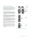
Keyboard and Mouse Connectors
The system uses a Personal System/2 (PS/2)-style key-
board and supports a PS/2-compatible mouse. Cables
from both devices attach to 6-pin, miniature Deutsche
Industrie Norm (DIN) connectors on the back panel of your
computer. The keyboard connector is on the bottom; the
mouse connector is on the top.
A PS/2-compatible mouse works identically to an industry-
standard serial mouse or bus mouse except that it has its
own dedicated connector, which frees up both serial ports
and does not require an expansion card. Circuitry inside the
Table B-3. Pin Assignments for the Serial Port
Connectors
Pin Signal I/O Definition
1 DCD I Data carrier detect
2 SIN I Serial input
3 SOUT O Serial output
4 DTR O Data terminal ready
5 GND N/A Signal ground
6 DSR I Data set ready
7 RTS O Request to send
8 CTS I Clear to send
9 RI I Ring indicator
Shell N/A N/A Chassis ground
1 — 13
14 — 25
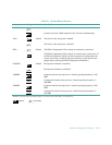
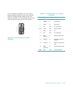
Table B-4. Pin Assignments for the Parallel Port
Connector
Pin Signal I/O Definition
1 STB# I/O Strobe
2 PD0 I/O Printer data bit 0
3 PD1 I/O Printer data bit 1
4 PD2 I/O Printer data bit 2
5 PD3 I/O Printer data bit 3
6 PD4 I/O Printer data bit 4
7 PD5 I/O Printer data bit 5
8 PD6 I/O Printer data bit 6
9 PD7 I/O Printer data bit 7
10 ACK# I Acknowledge
11 BUSY I Busy
12 PE I Paper end
13 SLCT I Select
14 AFD# O Automatic feed
15 ERR# I Error
16 INIT# O Initialize printer
17 SLIN# O Select in
18-25 GND N/A Signal ground