7-88 Dell PowerEdge 2100/180 and 2100/200 Systems User’s Guide
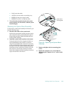
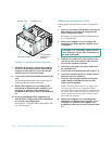
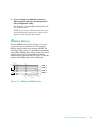
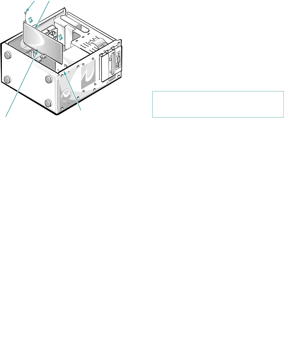
Figure 7-4. Installing an Expansion Card
7. When the card is firmly seated in the connector
and the card-mounting bracket is flush with the
brackets on either side of it, secure the bracket
with the screw you removed in step 4.
8. Connect any cables that should be attached to the
card.
See the documentation that came with the card for
information about its cable connections.
9. Replace the computer cover according to the
instructions in “Replacing the Computer Cover”
in Chapter 6, reconnect your computer and
peripherals to their power sources, and turn them
on.
10. If you are installing an EISA expansion card,
start the EISA Configuration Utility and add the
new card to your configuration.
See Chapter 5, “Using the EISA Configuration Util-
ity,” for instructions.
Removing an Expansion Card
Follow this general procedure to remove an expansion
card:
1. If you are relocating or permanently removing an
ISA expansion card, enter the change into the
EISA Configuration Utility.
See Chapter 5, “Using the EISA Configuration Util-
ity,” for instructions.
2. Remove the computer cover according to the
instructions in “Removing the Computer Cover”
in Chapter 6.
3. With the cover removed, lay the computer (left
side up) on a flat work surface so that you have
access to the expansion card slots.
4. If necessary, disconnect any cables connected to
the expansion card.
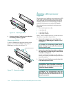
5. Unscrew the card-mounting bracket (Figure 7-3).
6. Grasp the expansion card by its outside corners,
and ease it out of its connector.
7. If you are removing the expansion card perma-
nently, install a metal filler bracket over the
empty card-slot opening.
NOTE: Installing filler brackets over empty card-
slot openings is necessary to maintain Federal
Communications Commission (FCC) certification of
the system. The brackets also keep dust and dirt out
of the computer and aid in proper cooling and air-
flow inside the computer.
8. Replace the computer cover according to the
instructions in “Replacing the Computer Cover”
in Chapter 6, reconnect your computer and
peripherals to their power sources, and turn them
on.
expansion card
mounting screw
card-edge connector
card-guide slots
(inside front of
c
omputer)
CAUTION: See “Protecting Against Electro-
static Discharge” in the safety instructions at
the front of this guide.


