7-94 Dell PowerEdge 2100/180 and 2100/200 Systems User’s Guide
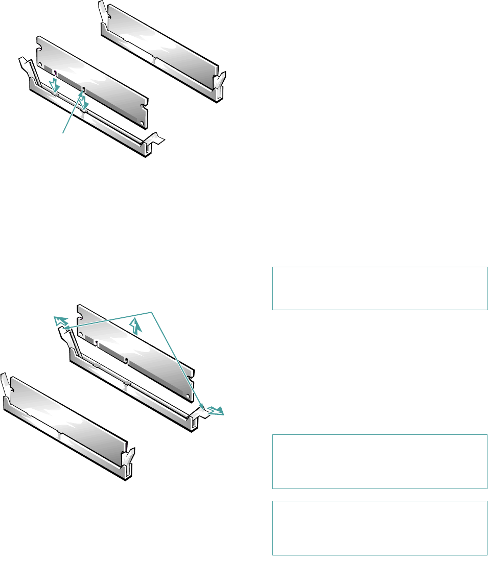
Figure 7-6. Installing a DIMM
4. Continue with step 5 of the previous subsection,
“Performing a Memory Upgrade.”
Removing a DIMM
To remove a DIMM, press down and outward on the
ejectors on each end of the DIMM socket until the
DIMM pops out of the socket (Figure 7-7).
Figure 7-7. Removing a DIMM
Installing a Microprocessor
Upgrade
The microprocessor is installed in a zero insertion force (ZIF)
socket on the system board to allow you to easily upgrade
your system with a more powerful microprocessor as your
computing needs increase. Use the following procedure to
remove the old microprocessor and install the upgrade.
The following items are included in a microprocessor
upgrade kit:
• The new microprocessor chip
• A new heat sink
• A new heat sink clip
• A new snap-in badge
NOTE: Dell recommends that only a technically knowl-
edgeable person perform this procedure.
1. Remove the computer cover according to the
instructions in “Removing the Computer Cover”
in Chapter 6.
2. Remove the system board assembly according to
the instructions in “Removing the System Board
Assembly” in Chapter 6.
Lay the system board assembly on a flat work sur-
face so you can easily access the microprocessor and
heat sink assembly.
3. Remove the metal clip that secures the heat sink
to the microprocessor socket.
cutout
2.
2.
CAUTION: See “Protecting Against Electro-
static Discharge” in the safety instructions at
the front of this guide.
CAUTION: Never remove the heat sink from a
microprocessor unless you intend to remove the
microprocessor. The heat sink is necessary to main-
tain proper thermal conditions.
WARNING: The microprocessor chip and
heat sink can get extremely hot. Be sure the
microprocessor has had sufficient time to cool
before you touch it.
