


Hardware Configuration Features B-129
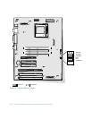
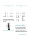
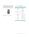
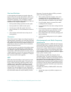
If you reconfigure your hardware, you may need pin
number and signal information for the video connector.
Figure B-7 illustrates the pin numbers for the video
connector, and Table B-7 lists and defines the pin assign-
ments and interface signals for the video connector.
Figure B-7. Pin Numbers for the Video
Connector
1 — 5
6
10
11 — 15
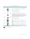
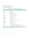
Table B-7. Pin Assignments for the Video
Connector
Pin Signal I/O Definition
1 RED O Red video
2 GREEN O Green video
3 BLUE O Blue video
4 NC N/A No connection
5-8, 10 GND N/A Signal ground
9 DDC N/A Vcc
11 NC N/A No connection
12 DDC
data out
O Monitor detect data
13 HSYNC O Horizontal synchro-
nization
14 VSYNC O Vertical synchroniza-
tion
15 DDC
clock out
O Monitor detect clock
Shell N/A N/A Chassis ground