


27 Mini Tower Computer
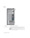
Removing the Computer Cover
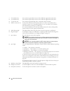
CAUTION: Before you begin any of the procedures in this section, follow the safety instructions located in the
Product Information Guide.
CAUTION: To guard against electrical shock, always unplug your computer from the electrical outlet before
removing the computer cover.
1
Follow the procedures in "Before You Begin" on page 21.
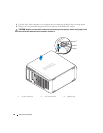
2
Lay the computer on its side as shown in the illustration.
3
Locate the cover release latch shown in the illustration. Then, slide the release latch back as you lift the
cover.
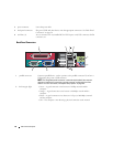
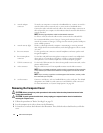
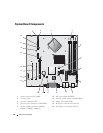
3 network adapter
connector
To attach your computer to a network or broadband device, connect one end of a
network cable to either a network jack or your network or broadband device.
Connect the other end of the network cable to the network adapter connector on
the back panel of your computer. A click indicates that the network cable has been
securely attached.
NOTE: Do not plug a telephone cable into the network connector.
For VPro to work, the network cable must be connected to the onboard NIC.
It is recommended that you use Category 5 wiring and connectors for your
network. If you must use Category 3 wiring, force the network speed to 10 Mbps to
ensure reliable operation.
4 network activity light Flashes a yellow light when the computer is transmitting or receiving network
data. A high volume of network traffic may make this light appear to be in a steady
"on" state.
5 line-out connector Use the green line-out connector to attach headphones and most speakers with
integrated amplifiers.
6 line-in/microphone
connector
Use the blue and pink line-in/microphone connector to attach a record/playback
device such as a cassette player, CD player, or VCR.; or a personal computer
microphone for voice or musical input into a sound or telephony program.
7 USB 2.0 connectors (6) Use the back USB connectors for devices that typically remain connected, such as
printers and keyboards.
8 video connector Plug the cable from your VGA-compatible monitor into the blue connector.
NOTE: If you purchased an optional graphics card, this connector will be covered by
a cap. Connect your monitor to the connector on the graphics card. Do not remove
the cap.
NOTE: If you are using a graphics card that supports dual monitors, use the y-cable
that came with your computer.
9 serial connector Connect a serial device, such as a handheld device, to the serial port. The default
designations are COM1 for serial connector 1 and COM2 for serial connector 2.
For more information, see "System Setup Options" on page 281.