


24-port NWay Ethernet Switch User’s Guide
18 Identifying External Components
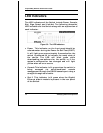
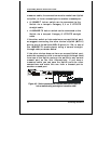
LED Indicators
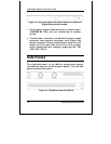
The LED indicators of the Switch include Power, Console,
Slot, Giga, Speed, and Link/Act. The following shows the
LED indicators for the Switch along with an explanation of
each indicator.
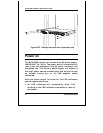
Figure 3-9. The LED indicators
♦
Power This indicator on the front panel should be
colored amber during the Power-On Self Test (POST).
It will light green approximately 2 seconds after the
switch is powered on to indicate the ready state of
the device. The LED will blink green while
downloading new software for the switch, or if the
system’s configuration has changed and will light
yellow when an error occurs.
♦
Console This indicator is lit green when the switch is
being managed via out-of-band/local console
management through the RS-232 console port using a
straight-through serial cable.
♦
Slot 2 This indicator is lit green when the Gigabit
Ethernet slide-in module is present in the rear panel
of the Switch.