


24-port NWay Ethernet Switch User’s Guide
Connecting The Switch
21
1X must remain vacant; if the bottom Uplink port is in use,
Port 2X cannot be used.
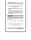
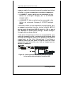
Figure 4-1. Switch connected to an End Nod
The LED indicators for the port the end node is connected
to are lit according to the capabilities of the NIC. If LED
indicators are not illuminated after making a proper
connection, check the PC’s LAN card, the cable, switch
conditions, and connections.
The following LED indicator states are possible for an end
node to switch connection:
1.
The 100M LED indicator comes
ON
for a 100 Mbps
and stays
OFF
for 10 Mbps.
2.
The Link/Act LED indicator lights up upon hooking
up a PC that is powered on.
Switch to Hub or Switch
These connections can be accomplished in a number of
ways. The most important consideration is that when
using a normal, straight-through cable, the connection
should be made between a normal crossed port (Port 1X, 2X,
etc.) and an Uplink (MDI-II) port. If you are using a