


137
Programming
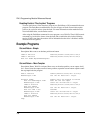
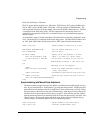
Knife Travel Distance = 20 inches
PLS.0 is used to initiate Index.0 every 100 inches. PLS.0 has an “ON” point at 0.000 inches
and an “OFF” point at 90.000 inches. PLS.0 has a rollover position of 100.000 inches. The
rollover position is used to set the part length. The source for PLS.0 is the master axis. The PLS
is configured in the PLS setup screen. The PLS output does not necessarily need to be
connected to an output line on the drive or module because it is used within the program to
initiate an index.
An Index PLS is used to fire the cutoff knife. The Index PLS is connected to Output #1 on the
drive. The Index PLS is configured in the index setup screen. The Index PLS for Index.1 has
an “ON” point 2.000 inches into the index and an “OFF” point 18 inches into the index.
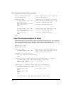
Home.0.Initiate ‘Sensor,Offset=1.000in,Vel=-5.0 in/s
MasterAxis.DefineHome=ON ‘Set the master position to 0.0
PLS.0.Enable=ON ‘Turn on PLS.0
Do While (TRUE) ‘Repeat until the program is halted
Wait For DriveInput.1=ON ‘Input 1 is used as a “hold” input.
If PLS.0.Status = ON Then ‘If the PLS is already on you are too
late.
ModuleOutput.4=ON‘Set a “Too Late” out-
put
End‘Drop out of the program
Endif
Wait For PLS.0.Status=ON ‘Start the Index when PLS.0 goes on
‘(every 100 inches).
Index.1.Initiate ‘Incremental,Sync,Dist=20.0in,Vel=1.0in/
in
Index.0.Initiate ‘Absolute,Sync,Posn=0.0in,Vel=2.0in/in
Wait For Index.AnyCommandComplete
Loop
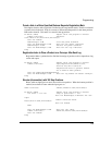
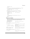
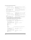
Synchronized Jog with Manual Phase Adjustment
The motor controls a lugged conveyor belt which is synchronized to another lugged conveyor
belt. Jog.0 is configured as a “Synchronized” jog using the setup software. The program first
homes the follower and then waits for an input from a sensor on the master axis lugs. When
the input comes on the follower starts the synchronized jog. If the home is setup correctly the
follower will be in perfect phase when it gets up to speed. If the follower gets out of phase
with the master the operator can manually bring the it back into phase using “Advance” and
“Retard” inputs. The program adjusts the phase of the follower axis by adjusting the jog
velocity (Jog.0.Vel) when the operator hits one of the phasing inputs.
Home.0.Initiate ‘Sensor,Offset=2.25in,Vel=10in/s
Jog.0.Vel=1.000 ‘follower inches/master inch