


220
FM-3 Programming Module Reference Manual
Note
If the friction loading of your system varies when operating at constant speed, due to a
load or spring load that changes as the motor rotates, use the lowest value measured.
3. Repeat Step 1 using a velocity at least two times the low speed.
4. While at speed, note the Torque Command Actual value (TCH).
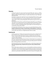
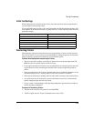
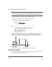
5. Use the following formula to calculate the friction:
Where:
T
CH
= Torque Command Limited value at higher speed
T
CL
= Torque Command Limited at lower speed
RPM
H
= Higher RPM (velocity)
RPM
L
= Lower RPM (velocity)
FV = Friction value
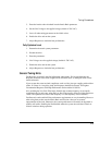
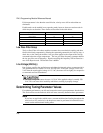
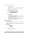
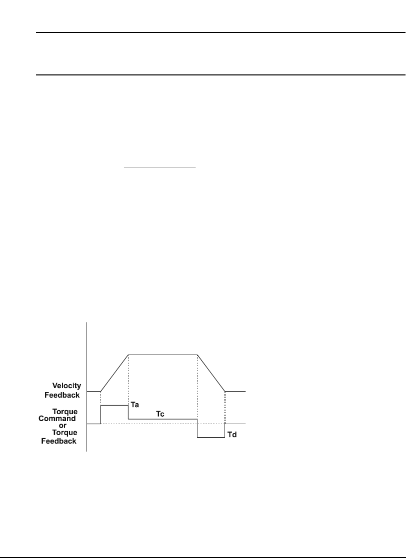
The figure below shows the relationship of Torque Command to the Velocity Feedback.
There is increased torque during the Accel ramp (Ta), constant torque (Tc) during the
constant velocity portion of the ramp and decreased torque (Td) during the decel ramp.
Figure 94: Trapezoidal Velocity Waveform with Torque Waveform
Determining Inertia Ratio
Actual system Inertia Ratio is determined by accelerating and decelerating the load with a
known ramp while measuring the torque required.
LH
CLCH
RPM - RPM
)T - (T
F
V )100(=