


33
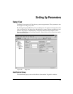
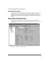
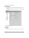
Setting Up Parameters
Encoder Scaling Check Box
This check box enables the Scaling parameter of the Drive Encoder Output.
Encoder Scaling
This parameter defines the encoder resolution (lines per revolution) of the drive's encoder
output. This feature allows you to change the drive encoder output resolution in increments
of 1 line per revolution up to the density of the encoder in the motor. If the Encoder Output
Scaling parameter is set to a value higher than the motor encoder density, the drive encoder
output density will equal that of the motor encoder.
Positive Direction Group
The Positive Direction group consists of a clockwise (CW) Motor Rotation Radio Button or
a counter-clockwise (CCW) Motor Rotation Radio Button.
The motion will move in either CW direction or counter-clockwise CCW direction.
Perspective of rotation is defined as you face the motor shaft from the front of the motor.
CW Motor Rotation Radio Button
Select this radio button for applications in which CW motor rotation is considered to be
motion in the positive direction (increasing absolute position).
CCW Motor Rotation Radio Button
Select this radio button for applications in which CCW motor rotation is considered to be
motion in the positive direction (increasing absolute position).
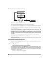
Update Rate Group
This parameter configures the interrupt interval for the FM-3 processor. This defines how
often the motion program is interrupted and the Control Loop is processed. In the Control
Loop, the feedback information is processed and a new position command is generated. Also
in the Control Loop, the I/O is scanned. After Control Loop is complete, all messages are
handled. Messages are Modbus data, DeviceNet data, Keypad/Display information, and are
only processed if a message is waiting. If no device is querying data from the FM-3 or sending
data to the FM-3, then messages do not take up any time. Once messages have been
processed, the remainder of the interrupt is dedicated to running the motion programs of user
programs.
Available selections for Trajectory Update are 800, 1200, and 1600 microseconds. The longer
the update, the more time is dedicated to the user programs, and the less time dedicated to
servo performance. The shorter the update , the more precise the servo performance, but less
time is available to process user programs. Diagnostics are available on the Status Online tab
when online with the device to help select the ideal setting. (See description of Control Loop
Group of online parameters for further information)